Cryopump

a cryopump and vacuum pump technology, applied in the field of cryopump, can solve the problems of lower pumping speed of these gases, achieve the effects of improving the isolation of adsorbent materials, increasing the capacity of condensed type ii gases, and reducing the temperature of arrays

Active Publication Date: 2013-11-28
EDWARDS VACUUM LLC
View PDF21 Cites 16 Cited by
  • Summary
  • Abstract
  • Description
  • Claims
  • Application Information

AI Technical Summary

Benefits of technology

[0018]Advantages of a cryopump having the large-area top plate described herein include increased capacity of condensed Type II gases before regeneration of the cryopump is needed. Another advantage of the large-area top plate is improved isolation of the adsorbent material from the Type II gases, preserving the adsorbent material for the Type III gases. The large-area top plate is particularly advantageous with the frontal baffle plate described above. The frontal baffle plate in combination with the large-area top plate allows less radiation from the process chamber to reach the second stage array of baffles than conventional frontal arrays that use sputter plates. The decreased radiation decreases the temperature of the array of the baffles / top plate, and particularly lowers the temperature of the baffle / top plate closest to the frontal baffle plate and the Type II condensed gas that is present on the baffle / top plate closest to the frontal baffle plate. The large-area top plate is capable of capturing a greater volume of condensed gases while maintaining an acceptable temperature of the surface of the condensed gas.

Problems solved by technology

However, the current state of the art sputter plates severely restrict Type II and Type III gases to the second stage cryopanels compared to the chevrons, which results in lower pumping speeds for these gases.

Method used


Image

  • Cryopump
  • Cryopump
  • Cryopump

Examples


Embodiment Construction

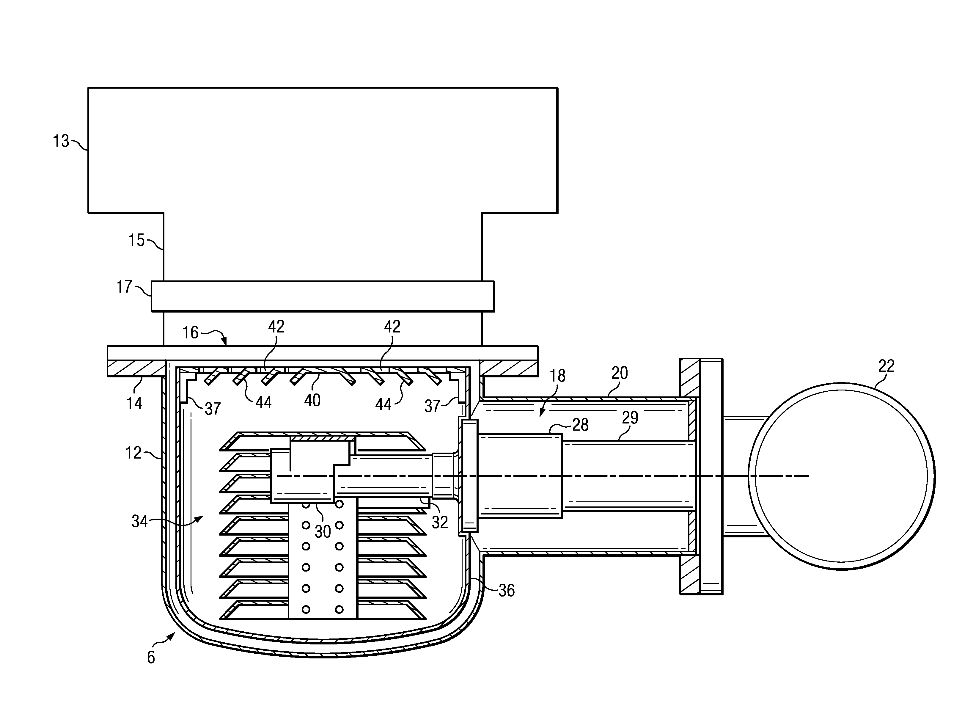
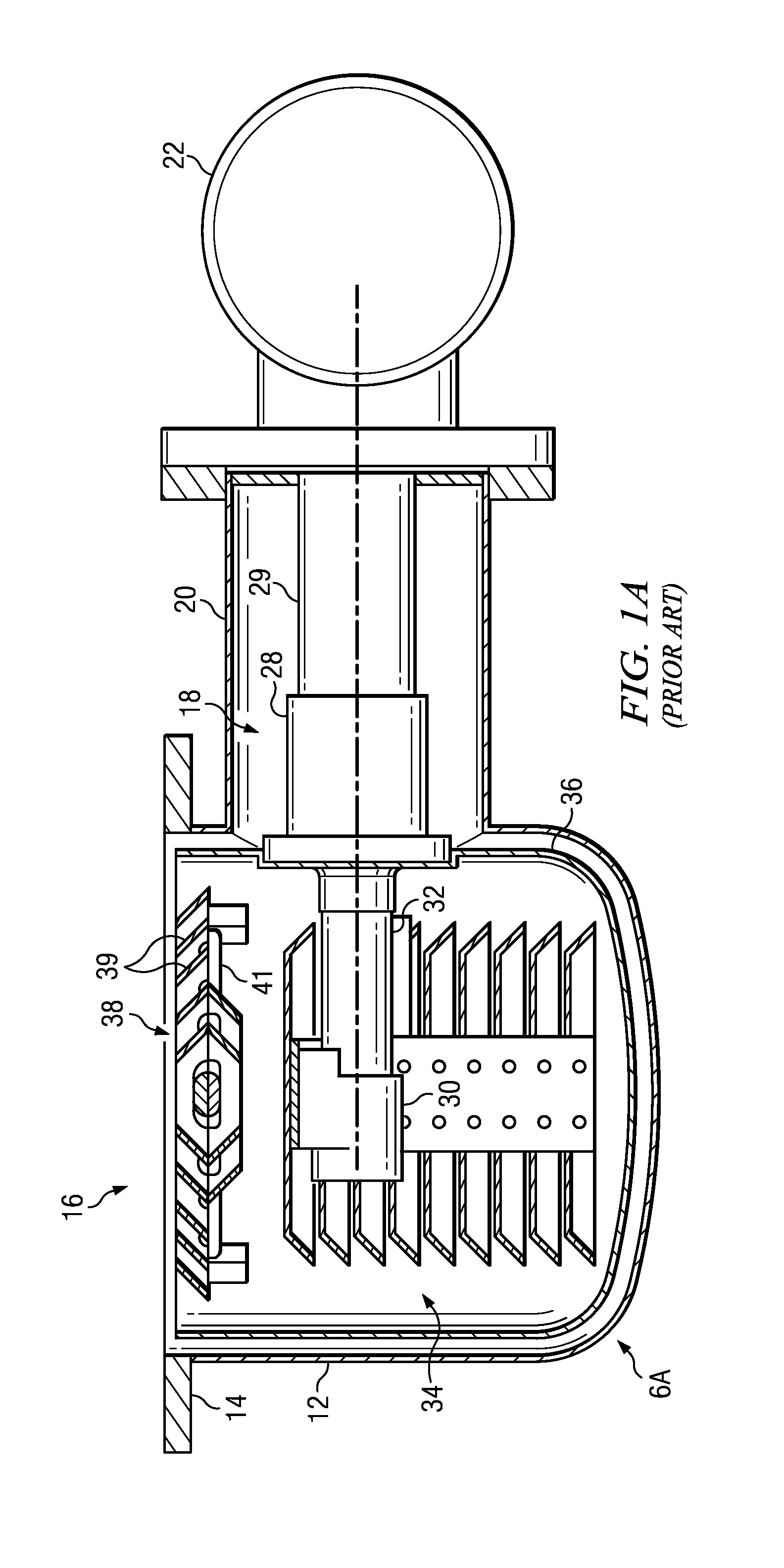
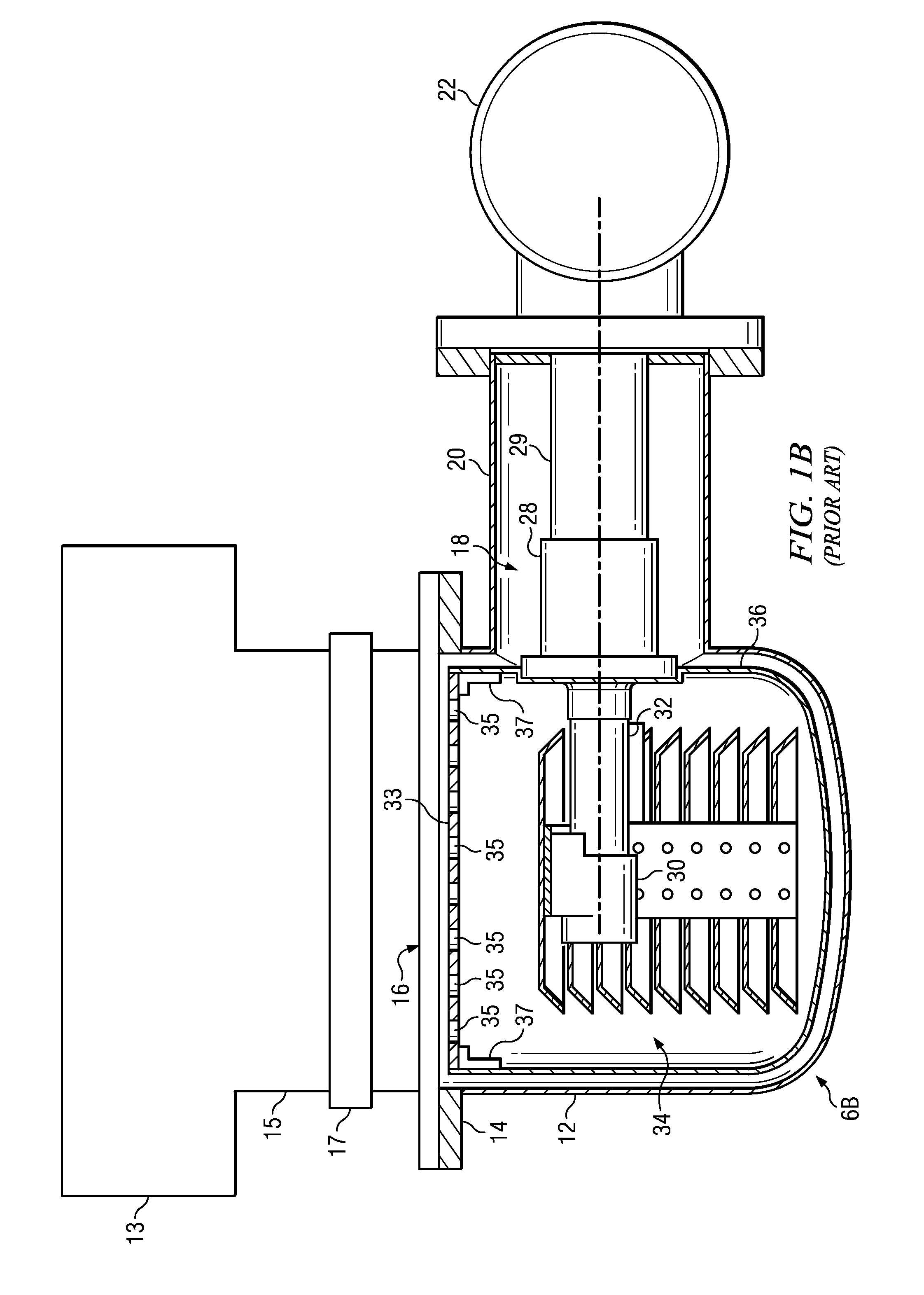
[0042]A description of example embodiments of the invention follows. A cross-section side view of prior art circular cryopumps 6A and 6B attached to a process chamber 13 is shown in FIGS. 1A and 1B, respectively. The cryopumps 6A and 6B include a cryopump housing 12 which may be mounted either directly to the process chamber along flange 14 or to an intermediate gate valve 17 between it and the process conduit 15 which is connected to the process chamber 13. The conduit 15 includes a gate valve 17 which may be employed to isolate the cryopump 6 from the process chamber 13. The cryopumps 6A and 6B are capable of pumping the process chamber 13. The cryopumps 6A and 6B include a cryopump housing 12 bolted to conduit 15, which is coupled to the process chamber 13. The front opening 16 in the cryopump housing 12 communicates with the circular opening in the process chamber 13. A two stage cold finger 18 of a refrigerator protrudes into the cryopump housing 12 through a cylindrical portio...


PUM

PropertyMeasurementUnit
angleaaaaaaaaaa
angleaaaaaaaaaa
angleaaaaaaaaaa

Abstract

A cryopump has a simple-to-manufacture frontal baffle plate with improved gas distribution and has a large-area second-stage array plate to capture Type II gases. The cryopump has a first-stage frontal baffle plate having orifices and flaps bent from and attached to the orifices. The cryopump has a second-stage top plate that is larger in area than cooling baffles of the second stage array.

Description

RELATED APPLICATION[0001]This application claims the benefit of U.S. Provisional Application No. 61 / 441,027, filed on Feb. 9, 2011.[0002]The entire teachings of the above application are incorporated herein by reference.BACKGROUND OF THE INVENTION[0003]Cryopumps currently available, whether cooled by open or closed cryogenic cycles, generally follow the same design concept. A low temperature second stage cryopanel array, usually operating in the range of 4-25 K, is a primary pumping surface. This surface is surrounded by a high temperature radiation shield usually operated in the temperature range of 40-130 K, which provides radiation shielding to the lower temperature array. The radiation shield generally comprises a housing which is closed except at a frontal cryopanel array positioned between the primary pumping surface and the chamber to be evacuated. This higher temperature, first stage, frontal array serves as a pumping site for high boiling point gases such as water vapor, kn...

Claims


Application Information

Patent Timeline
Patent Type & Authority Applications(United States)
IPC IPC(8): B01D8/00F04B37/08
CPCB01D8/00F04B37/08Y10T29/49236
Inventor SYSSOEV, SERGEIBARTLETT, ALLEN J.CASELLO, JOHN J.WELLS, JEFFREY A.EACOBACCI, JR. MICHAEL J.
Owner EDWARDS VACUUM LLC
Why Eureka
Try Eureka