LED bypass and control circuit for fault tolerant LED systems

Active Publication Date: 2013-11-28
TEXAS INSTR INC
View PDF5 Cites 43 Cited by
  • Summary
  • Abstract
  • Description
  • Claims
  • Application Information

AI Technical Summary

Benefits of technology

[0005]In a preferred embodiment of the present invention, a light system is disclosed. The light system includes a plurality of series connected light emitting diodes. Each of a plurality of transistors has a control terminal and has a current path coupled in parallel with a respective light e

Problems solved by technology

As such, the series connection or string of LEDs is sus

Method used


Image

  • LED bypass and control circuit for fault tolerant LED systems
  • LED bypass and control circuit for fault tolerant LED systems
  • LED bypass and control circuit for fault tolerant LED systems

Examples


Embodiment Construction

[0018]The preferred embodiments of the present invention provide significant advantages over LED lighting systems of the prior art as will become evident from the following detailed description.

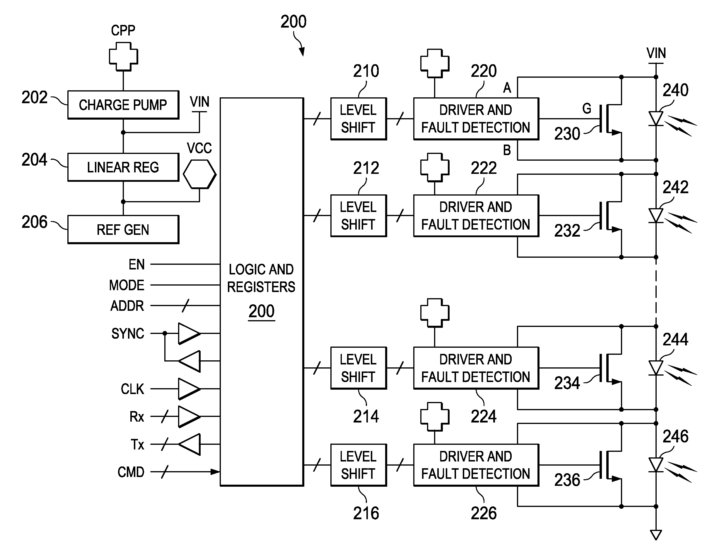
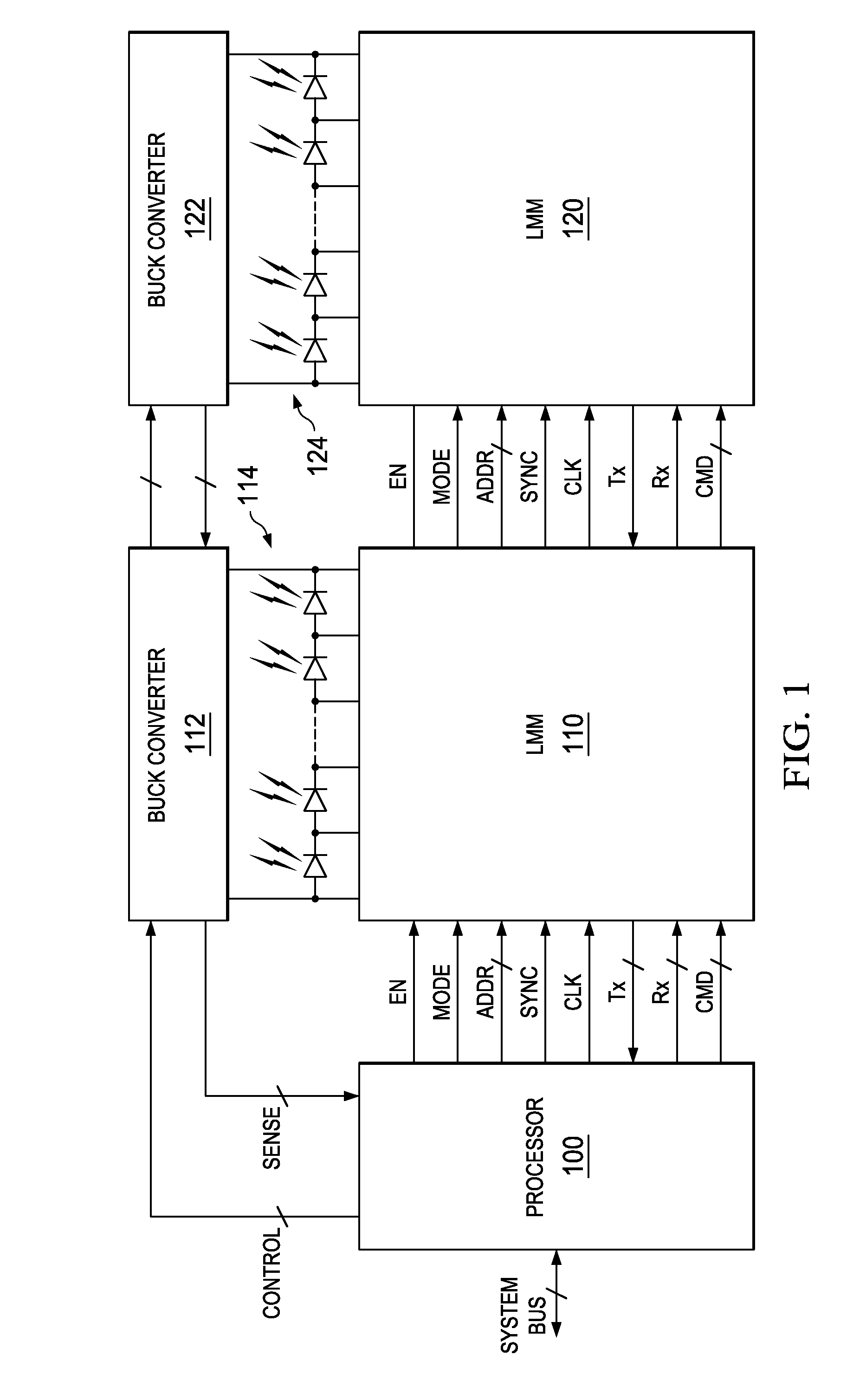
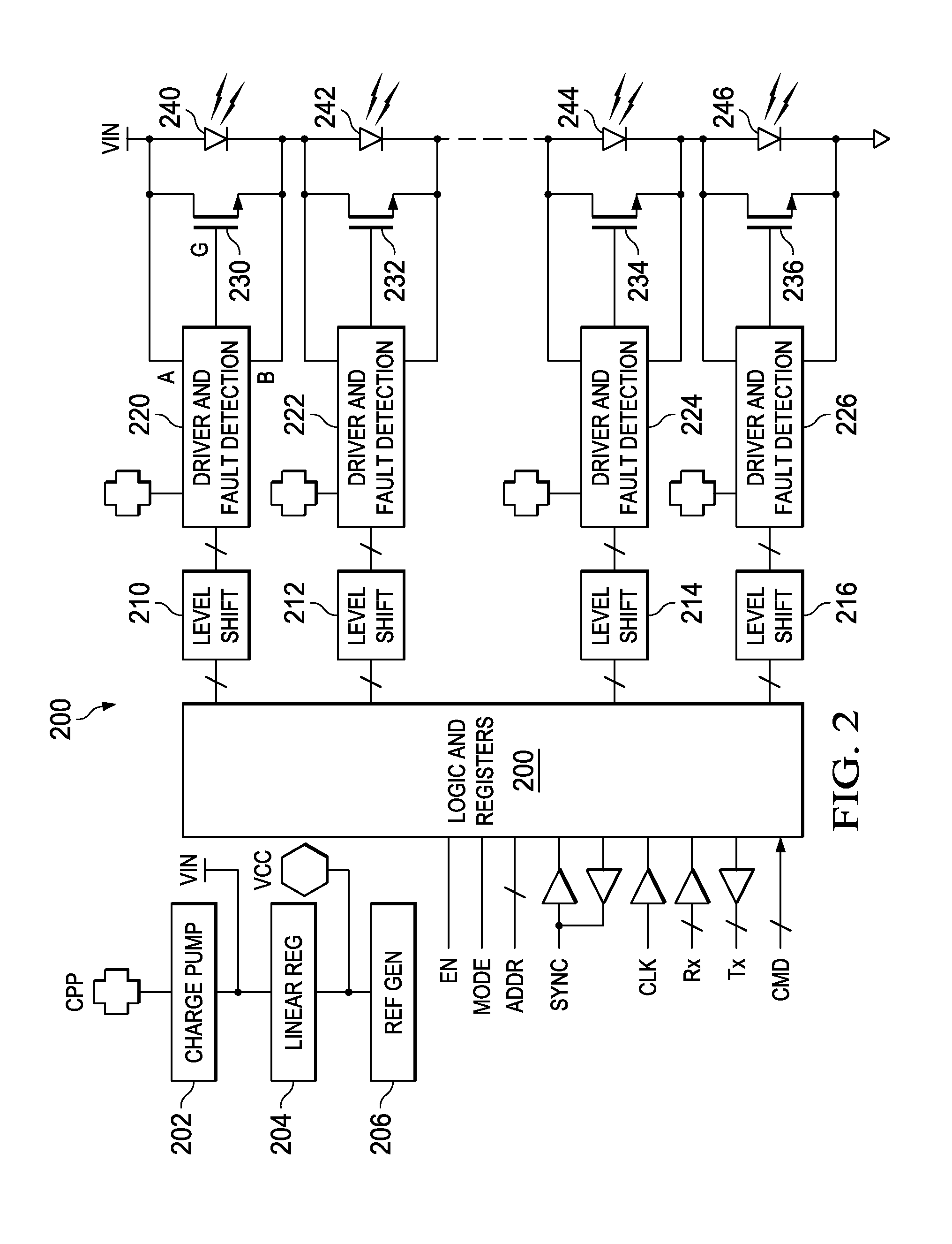
[0019]Referring to FIG. 1, there is a LED lighting system of the present invention which may be used for automotive lighting, home lighting, security lighting, or other applications where fault tolerant operation is desirable. The lighting system includes a processor 100 which is preferably coupled to a system has to receive control signals. The processor 100 is coupled to LED Matrix Manager (LMM) circuits 110 and 120 to provide enable (EN), synchronization (SYNC) and clock (CLK) signals. The processor 100 and the LMM circuits 110 and 120 include universal asynchronous receiver / transmitter (UART) circuits and communicate via transmit (Tx) and receive (Rx) signal lines. Synchronization signal SYNC synchronizes all PWM counters 400 (FIG. 4) of each LMM. Mode signal MODE determines whether proce...


PUM


Abstract

A light system (FIG. 2) is disclosed. The light system includes a plurality of series connected light emitting diodes (240-246). Each of a plurality of switching devices (230-236) has a control terminal and each has a current path coupled in parallel with a respective LED. A plurality of fault detector circuits (220-226) are each coupled in parallel with a respective light emitting diode. Each fault detector circuit has a first comparator (FIG. 7,704) arranged to compare a voltage across the respective light emitting diode to a respective first reference voltage (708). When a fault is defected, a control signal is applied to the control terminal to turn on a respective switching device of the plurality of switching devices.

Description

BACKGROUND OF THE INVENTION[0001]This application claims the benefit under 35 U.S.C. §119(e) of Provisional Appl. No. 61 / 650,099, filed May 22, 2012 (TI-72192PS), which is incorporated herein by reference in its entirety[0002]Embodiments of the present invention relate to a light emitting diode (LED) bypass and control circuit for fault tolerant LED lighting systems.[0003]Light emitting diode (LED) lighting systems are presently used for many applications such as automobiles, homes, businesses, and security systems. LED lighting systems provide illumination more efficiently than incandescent lighting systems, since they expend much less power in heat generation and are ranch more reliable. LED lighting systems are also much more flexible than fluorescent lighting systems, since they are more tolerant to environmental conditions such as shock, contamination, and temperature. Moreover, they may be operated with controlled duty cycles to adjust brightness. LED lighting systems are ofte...

Claims


Application Information

Patent Timeline
IPC IPC(8): H05B33/08H05B44/00
CPCH05B33/089H05B45/48H05B45/10H05B45/54H05B45/375
Inventor DENICHOLAS, JOSEPH V.TSAO, PERRYGOELTNER, CHRISTOPHHERRINGTON, DANIEL ROSSMASSON, JAMESPATTERSON, JAMESBERNS, WERNER
Owner TEXAS INSTR INC
Why Eureka
Try Eureka