Measurement device

a measurement device and measurement technology, applied in measurement devices, instruments, electrical testing, etc., can solve the problems of reducing the accuracy of measuring potentials of devices under test, unable to observe accurate change in voltage data, and inevitably generated leakage current, so as to achieve reduce leakage current. , the effect of long-term accurate measurement of voltag

Active Publication Date: 2013-11-28
SEMICON ENERGY LAB CO LTD
View PDF8 Cites 24 Cited by
  • Summary
  • Abstract
  • Description
  • Claims
  • Application Information

AI Technical Summary

Benefits of technology

[0025]In accordance with one embodiment of the present invention, it is possible to provide a measurement device which allows long-term accurate measurement of voltage without adversely affecting a device under test, by ensuring a predetermined level of resistance to ESD and by reducing leakage current.
[0026]Further, in accordance with one embodiment of the present invention, it is possible to provide a measurement device in which a risk of ESD occurring between the FET for voltage detection and the protection circuit and a risk of adding a factor in causing leakage current are reduced as much as possible and which allows long-term accurate measurement of voltage without adversely affecting a device under test, by ensuring a predetermined level of resistance to ESD and by reducing leakage current.

Problems solved by technology

However, since these elements are each controlled by passing current from an input to an output, the leakage current is inevitably generated in accordance with the operation principle.
The generation of the leakage current in the elements for detection results in reducing accuracy of measuring potentials of devices under test.
In the case where such an OS-FET is used in an electrical circuit which is a device under test, with the use of a conventional probe, variation in voltage occurs because the leakage current of the probe is too high; hence, accurate change in voltage data cannot be observed.

Method used


Image

  • Measurement device
  • Measurement device
  • Measurement device

Examples


embodiment 1

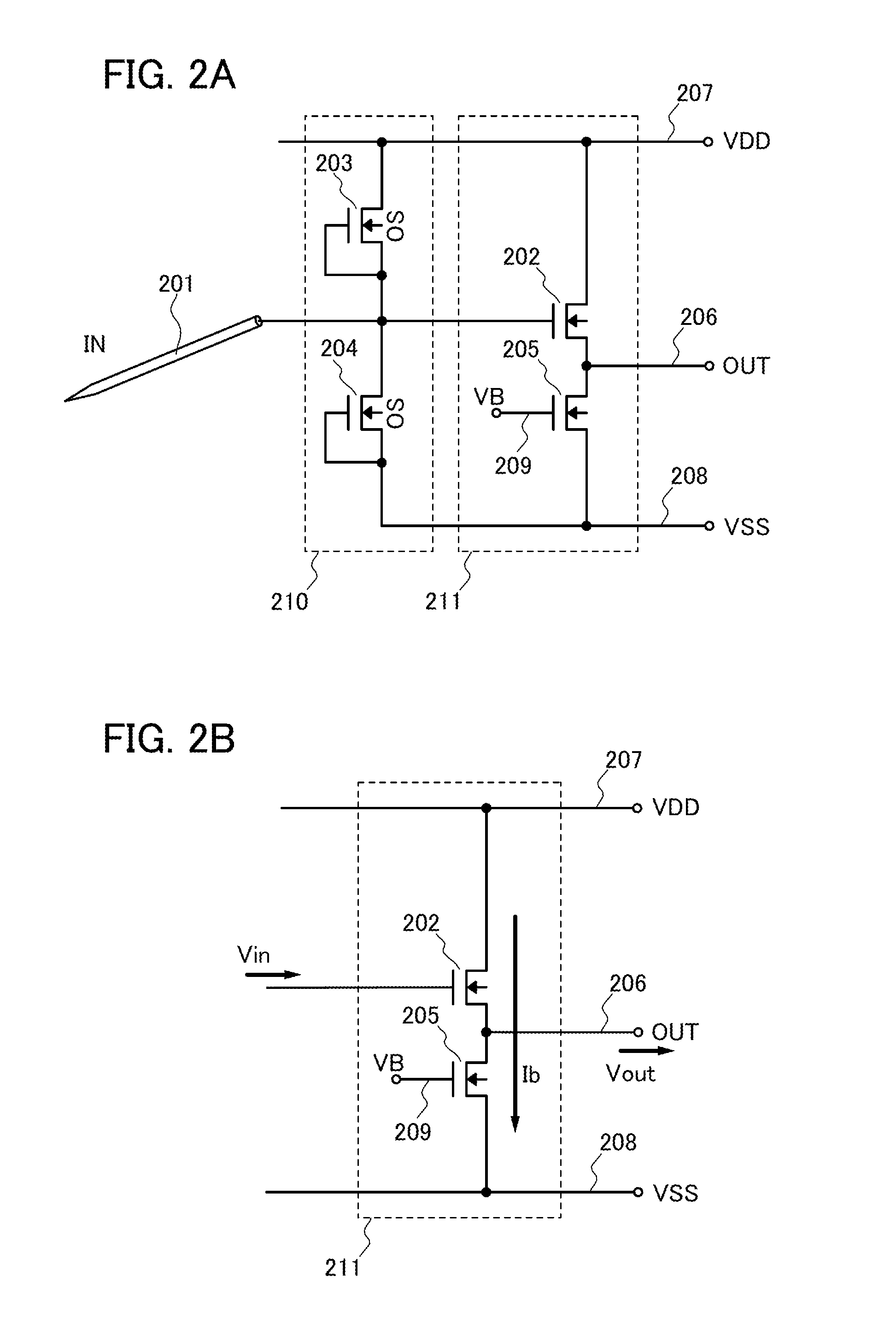
[0037]In this embodiment, one mode of a measurement device will be described with reference to FIGS. 2A and 2B.

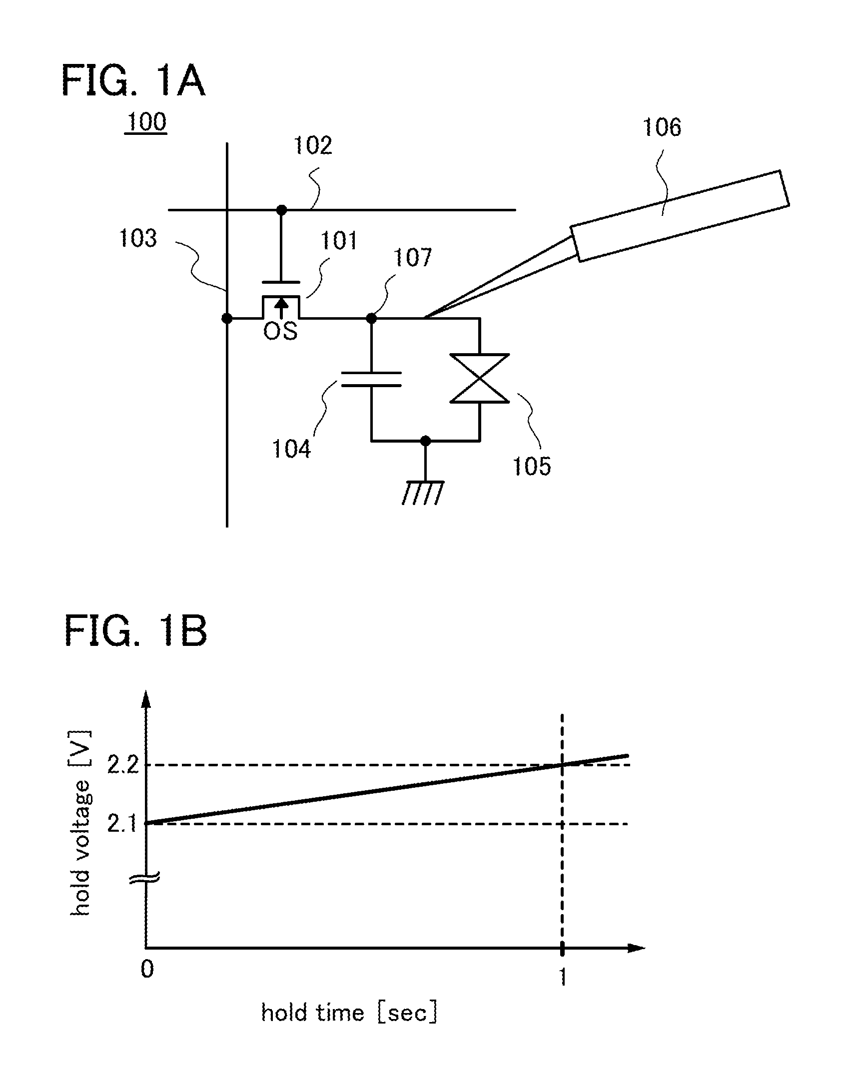
[0038]FIG. 2A shows a circuit configuration of an input end of a measurement device, or more specifically, an active probe. In this embodiment, the active probe includes a probe needle 201, a protection circuit portion 210, and a detecting portion 211. The detecting portion 211 in this embodiment includes a power supply line 207 for applying a high-potential-side potential (VDD), a power supply line 208 for applying a low-potential-side potential (VSS: ground potential), and an output terminal 206. Thus, the detecting portion 211 is a circuit having three output terminals.

[0039]By physical contact with a device under test, the probe needle 201 serves as an interface for inputting, to the measurement device, voltage of a portion where the probe needle contacts the device under test (hereinafter the portion is referred to as contact portion). Therefore, the probe needle 201 i...

embodiment 2

[0059]In Embodiment 1, the measurement device including the detecting portion having three output terminals is described. In this embodiment, a measurement device including a detecting portion having two output terminals will be described with reference to FIG. 3.

[0060]FIG. 3 shows a circuit configuration of an input end of a measurement device, or more specifically, an active probe. In this embodiment, the active probe includes a probe needle 301, a protection circuit portion 307, and a detecting portion 308. The detecting portion 308 in this embodiment includes a power supply line 306 for applying a high-potential-side potential (VDD) and an output terminal 305. Thus, the detecting portion 308 is a circuit having two output terminals.

[0061]The probe needle 301 is electrically connected to the detecting portion 308 via the protection circuit portion 307.

[0062]The detecting portion 308 includes a MOSFET 302. In this embodiment, the MOSFET 302 is an n-channel transistor. The MOSFET 3...

embodiment 3

[0068]In Embodiment 1, the case of using n-channel MOSFETs in the detection portion having three output terminals in the measurement device is described. In this embodiment, the case of using p-channel MOSFETs will be described with reference to FIG. 4.

[0069]FIG. 4 shows a circuit configuration of an input end of a measurement device, or more specifically, an active probe. In this embodiment, the active probe includes a probe needle 401, a protection circuit portion 410, and a detecting portion 411. The detecting portion 411 in this embodiment includes a power supply line 407 for applying a high-potential-side potential (VDD), a power supply line 408 for applying a low-potential-side potential (VSS: ground potential), and an output terminal 406. Thus, the detecting portion 411 is a circuit having three output terminals.

[0070]The probe needle 401 is electrically connected to the detecting portion 411 via the protection circuit portion 410.

[0071]The detecting portion 411 includes two ...


PUM


Abstract

To provide a measurement device which allows long-term accurate measurement of voltage without adversely affecting a device under test, by ensuring a predetermined level of resistance to ESD and reducing leakage current. A measurement device includes a probe needle for contacting a device under test, a first FET for detecting voltage of the device under test, and a protection circuit for protecting the first FET from static electricity. The protection circuit includes a second FET having an oxide semiconductor film as a channel formation region.

Description

BACKGROUND OF THE INVENTION[0001]1. Field of the Invention[0002]The present invention relates to a measurement device, and in particular, relates to a measurement device used for electrically measuring and checking an electrical circuit.[0003]2. Description of the Related Art[0004]For the purpose of operation verification tests or failure analysis, an active probe is used to measure internal voltages in integrated circuits of, for example, display devices typified by LSIs, LCDs, and OLEDs. An FET probe, which is a typical example of an active probe, includes a field effect transistor (FET) that is an active element and a passive element, and further, a power source is used. With an active probe having such a structure, higher input impedance (e.g., 1 MΩ or greater) and lower input capacitance (e.g., 1 pF or less) than a passive probe constituted by C (capacitor) and R (resistor) can be achieved, and a waveform can be observed while a device under test (DUT) is not adversely affected...

Claims


Application Information

Patent Timeline
Patent Type & Authority Applications(United States)
IPC IPC(8): G01R1/36
CPCG01R1/36
Inventor TAKAHASHI, KEIINOUE, NOBORU
Owner SEMICON ENERGY LAB CO LTD
Why Eureka
Try Eureka