Method for controlling the speed of brushless motors

a brushless electric motor and speed control technology, applied in the direction of electronic commutation motor control, instrumentation, base element modification, etc., can solve the problems of parasitic inductance becoming significant, distorting the measurement of electric current, and ineffective sensors, so as to improve the performance and robustness of the motor control, improve the accuracy of measurement, and achieve the effect of precise determination of the real voltag

Pending Publication Date: 2022-09-22
VITESCO TECH GERMANY GMBH
View PDF0 Cites 0 Cited by
  • Summary
  • Abstract
  • Description
  • Claims
  • Application Information

AI Technical Summary

Benefits of technology

[0022]An advantage of the present invention lies in the precise determination of the real voltage generated by the inductive part of a measuring resistor.
[0023]Yet another advantage of the present invention lies in the increase in the precision of measurement of the voltage generated by the resistive part of a measuring resistor.
[0024]Another advantage of the present invention lies in the increase in the performance and robustness of a motor control.
[0025]Yet another advantage of the present invention lies in the precise measurement of the voltage generated by the resistive part of a measuring resistor at lower cost.

Problems solved by technology

However, when the rotational speed of the motor is high, the sensors become ineffective.
Thus, for very low resistance values, the parasitic inductance becomes significant and distorts the measurement of the electric current.
Moreover, a distorted measurement of the voltage results in poor synchronization of the motor and therefore random and not very robust speed control.
This solution has many drawbacks because the differential filter is configured with respect to a parasitic inductance value provided by the supplier of the measuring resistor.

Method used


Image

  • Method for controlling the speed of brushless motors

Examples


Embodiment Construction

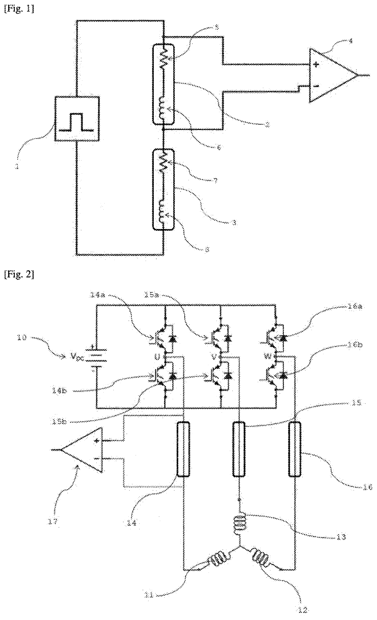
[0029]As indicated above, the invention is based on determining the voltage generated by the inductive part of a measuring resistor included in an electronic circuit.

[0030]FIG. 1 shows an electronic circuit comprising a signal generator 1, a resistor 2, a coil or stator winding 3 and a differential amplifier 4 at the terminals of the measuring resistor 2. The resistor 2 is connected to the signal generator 1 and to the stator winding 3, which is itself connected to the signal generator 1.

[0031]The signal generator 1 is able to deliver a signal to the electronic circuit so as to energize the electronic circuit. The signal generator 1 according to the invention generates a DC voltage signal. According to one embodiment of the invention, the signal generator 1 delivers a DC voltage step VDC of known value for a known period of time t.

[0032]The stator winding 3 allows a current to be generated when it is energized. The stator winding 3 comprises a resistive part 7 of resistance RS and a...


PUM


Abstract

Method for determining the voltage UL generated by the inductive part of a measuring resistor present in an electronic circuit including a signal generator, at least one stator winding connected to the signal generator and to the measuring resistor and a differential amplifier for the voltage across the terminals of the measuring resistor, the method including: a step of energizing the electronic circuit for a predetermined period of time t; a step of measuring the voltage UT across the terminals of the measuring resistor at the end of the energizing step; a step of determining the voltage UR generated by the resistive part of the measuring resistor at the end of the energizing step; and a step of determining the voltage UL generated by the inductive part of the measuring resistor as a function of the voltage UT and the voltage UR.

Description

FIELD OF THE INVENTION[0001]The present invention relates to a method for controlling the speed of a brushless electric motor and more particularly to a method for determining the voltage generated by the inductive part of a measuring resistor present in an electronic circuit of a motor.PRIOR ART[0002]Nowadays, brushless motors are widely used in industry because they have many advantages over DC motors. They have better performance and increased reliability. The brushless motor is particularly useful in motor vehicles comprising a combustion engine. The brushless motor has a very good power-to-weight ratio and replaces the DC motor especially when mass or rotational speed are important criteria.[0003]Brushless motors are synchronous and usually three-phase AC electrical machines. It is necessary to control the speed of a motor precisely, and this is usually achieved using Hall effect sensors. These sensors allow the position of the rotating field in the motor to be known precisely....

Claims


Application Information

Patent Timeline
Patent Type & Authority Applications(United States)
IPC IPC(8): G01R31/34H02P23/14G01R1/20G01R19/00
CPCG01R31/343H02P23/14G01R1/203G01R19/0084H02P6/00G01R19/0092
Inventor BOUKHRIS, KARIMMEDIOUNI, NASSIM
Owner VITESCO TECH GERMANY GMBH
Why Eureka
Try Eureka