Electronic device

a technology of electronic devices and electronic components, applied in the field of electronic devices, can solve the problems of increasing and achieve the effect of suppressing the increase in the size of the electronic devi

Inactive Publication Date: 2013-11-28
NEC CORP
View PDF7 Cites 21 Cited by
  • Summary
  • Abstract
  • Description
  • Claims
  • Application Information

AI Technical Summary

Benefits of technology

[0011]According to the present invention, it is possible to suppress an increase in the size of an electronic device capable of reproducing the sound with appropriate sound pressure for a target for which the sound is to be reproduced.

Problems solved by technology

As a result, the electronic device becomes larger.

Method used


Image

  • Electronic device
  • Electronic device
  • Electronic device

Examples


Embodiment Construction

[0022]Hereinafter, embodiments of the present invention will be described with reference to the drawings. In addition, the same components are denoted by the same reference numerals in all drawings, and explanation thereof will not be repeated.

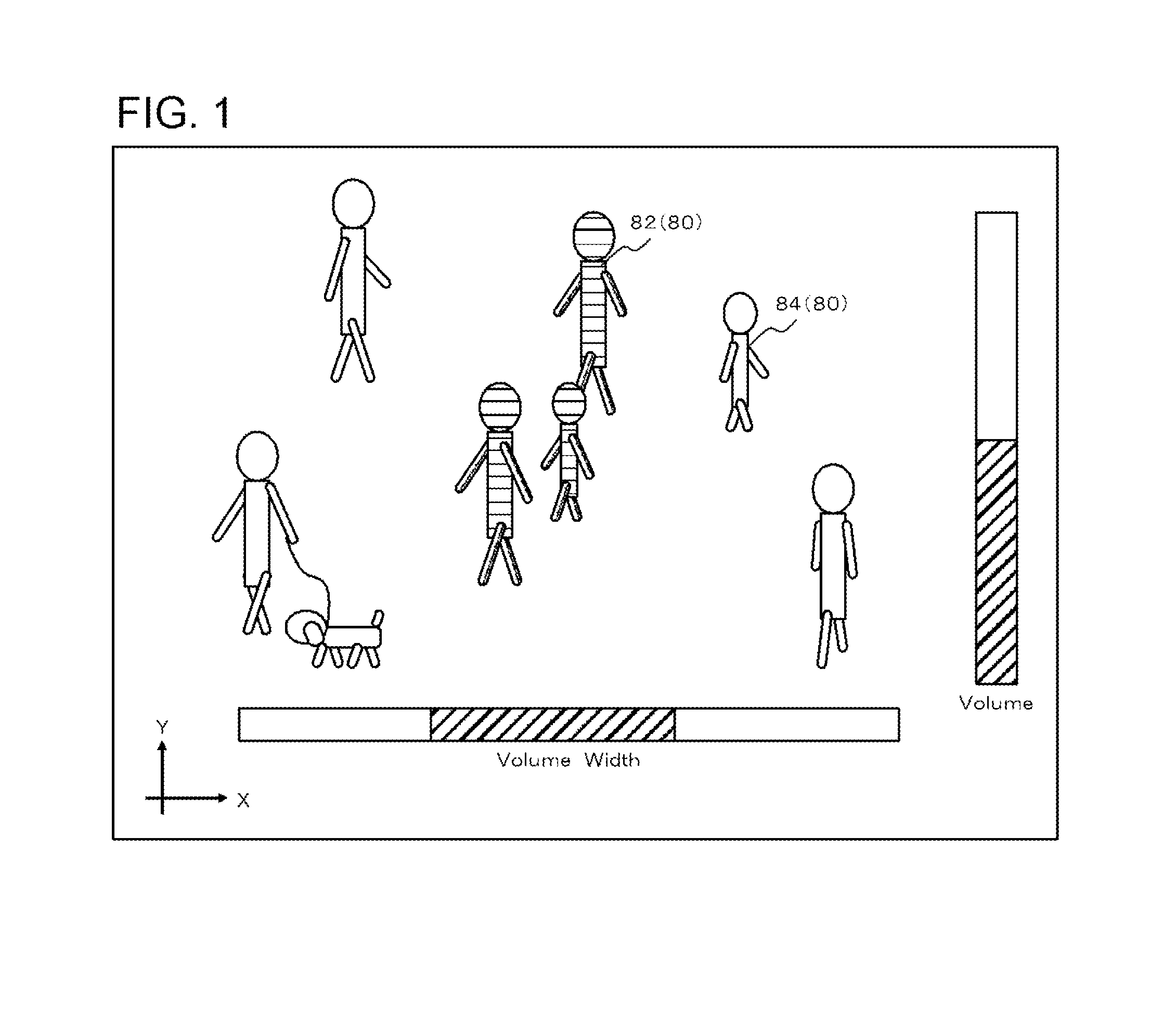
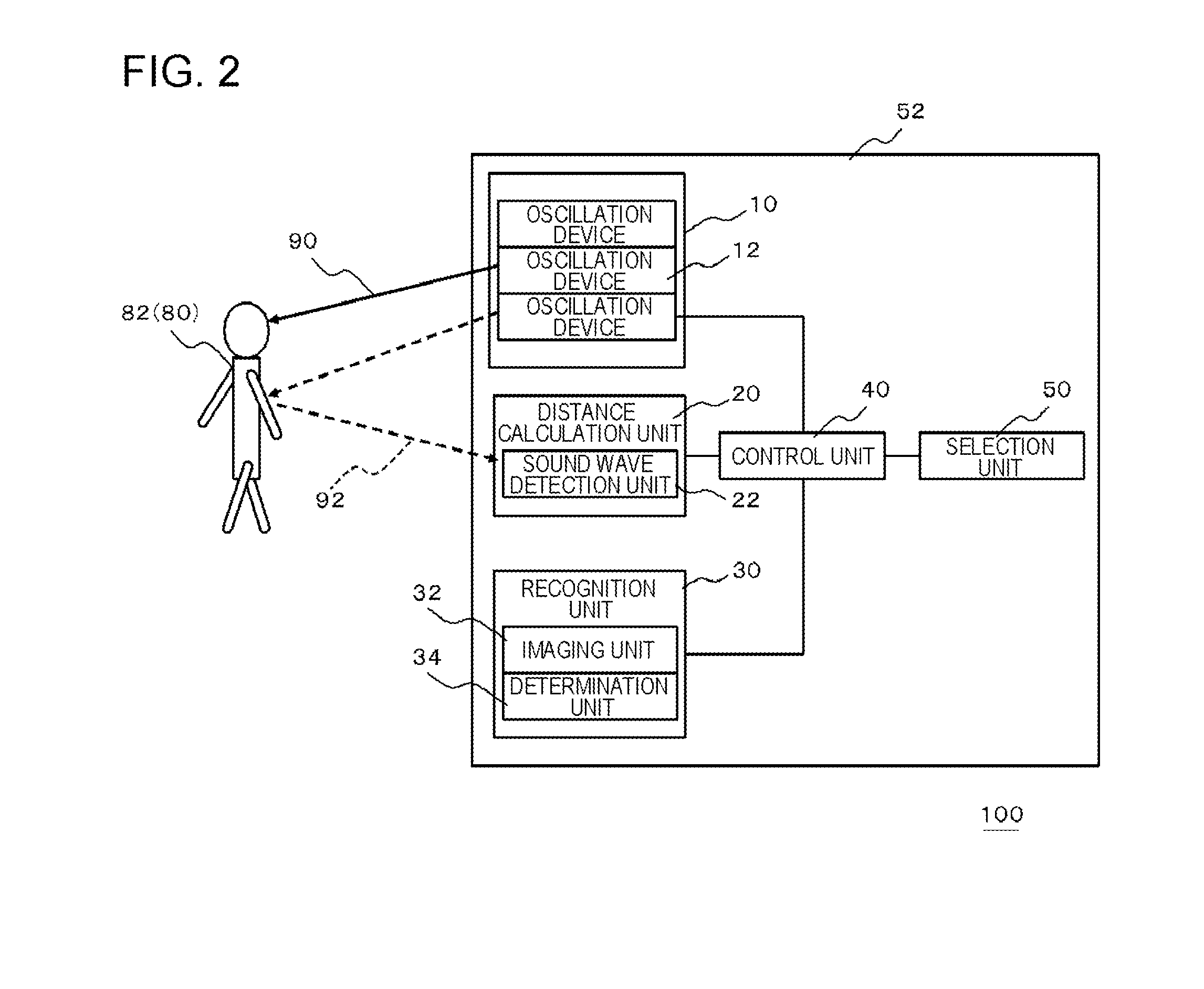
[0023]FIG. 1 is a schematic diagram showing an operation method of an electronic device 100 according to a first embodiment. In addition, FIG. 2 is a block diagram showing the configuration of the electronic device 100 shown in FIG. 1. The electronic device 100 according to the present embodiment includes an oscillation device 10, a recognition unit 30, a selection unit 50, a distance calculation unit 20, and a control unit 40. For example, the electronic device 100 is a mobile terminal apparatus, such as a mobile phone.

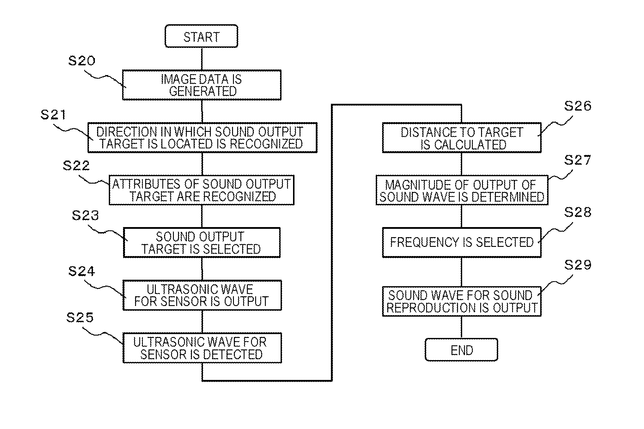
[0024]The oscillation device 10 outputs an ultrasonic wave 92 for a sensor and a sound wave 90 for sound reproduction. The recognition unit 30 recognizes a direction in which a sound output target for which the sound is to be o...


PUM


Abstract

There are provided an oscillation device that outputs a sound wave; a recognition unit that recognizes a direction in which sound output targets (80), for which a sound is to be output, are located; a selection unit that selects at least one of the sound output targets (80); a distance calculation unit that calculates a distance to the sound output target (80); and a control unit that controls the oscillation device to adjust sound pressure of the sound wave. The oscillation device outputs an ultrasonic wave for a sensor and a sound wave for sound reproduction. The distance calculation unit calculates a distance between the oscillation device and an object to be selected (82) by detecting the ultrasonic wave for a sensor reflected from the object to be selected (82) selected by the selection unit. The control unit adjusts the magnitude of the output of the sound wave for sound reproduction on the basis of the calculated distance between the oscillation device and the object to be selected (82).

Description

TECHNICAL FIELD[0001]The present invention relates to an electronic device that uses ultrasonic waves.BACKGROUND ART[0002]Various techniques for speakers have been studied. For example, a technique using an oscillation device that oscillates ultrasonic waves may be mentioned. A highly directional sound field can be formed by using an oscillation device, which oscillates ultrasonic waves, for sound reproduction of a speaker. As a technique for a speaker using ultrasonic waves, for example, techniques disclosed in Patent Documents 1 to 4 may be mentioned. The technique disclosed in Patent Document 1 is to form an audible region, which can be moved arbitrarily, by controlling the frequency or phase of the oscillating ultrasonic wave.[0003]The technique disclosed in Patent Document 2 controls the directivity by providing a plurality of speakers, which oscillate ultrasonic waves, inside the speaker cabinet and changing a sound signal to drive each speaker. The technique disclosed in Pate...

Claims


Application Information

Patent Timeline
Patent Type & Authority Applications(United States)
IPC IPC(8): H04R1/32
CPCH04R1/32H04N5/60H04R17/00H04R1/403H04R2217/03H04R2430/01H04R2430/20H04N21/42201H04N21/439H04N21/44218H04N21/41407H04N21/4223
Inventor YAGIHASHI, AYUMUKITATANI, KENICHIAOKI, HIROYUKIKATOU, YUMIMURAYAMA, ATSUHIKOSUGAHARA, SEIJI
Owner NEC CORP
Why Eureka
Try Eureka