Method for transmitting and method for receiving a channel state information reference signal in a distributed multi-node system

a multi-node system and channel state information technology, applied in signalling characterisation, wireless commuication services, site diversity, etc., can solve the problems of reducing the efficiency of the distributed multi-node system as a relatively low cell throughput and inefficient interference coordination in the cell edge, so as to reduce the complexity of implementation resulting from detecting a node by a user equipment and high cell throughput

Inactive Publication Date: 2013-11-28
LG ELECTRONICS INC
View PDF19 Cites 58 Cited by
  • Summary
  • Abstract
  • Description
  • Claims
  • Application Information

AI Technical Summary

Benefits of technology

[0037]According to the present specification, by defining a CSI-RS including a plurality of configurations and having power, which is not zero, a distributed multi node system including a plurality of nodes may be able to have high cell throughput and may be able to perform efficient interference coordination in a cell edge.
[0038]According to the present specification, by transmitting a CSI-RS designed to detect a node, implementation complexity resulted from detecting a node by a user equipment can be reduced.
[0039]According to the present specification, by transmitting control information designed to determine a valid antenna, an overhead resulted from time and calculation taken from determining a valid antenna per each antenna node of a user equipment or a base station can be reduced.

Problems solved by technology

Yet, if the number of node in a cell is greater than 8, it brings about such a result restricting performance of the distributed multi-node system as a relatively low cell throughput, inefficient interference coordination in a cell edge, or the like.

Method used


Image

  • Method for transmitting and method for receiving a channel state information reference signal in a distributed multi-node system
  • Method for transmitting and method for receiving a channel state information reference signal in a distributed multi-node system
  • Method for transmitting and method for receiving a channel state information reference signal in a distributed multi-node system

Examples


1st embodiment

1st Embodiment

[0116]In the following description, a method of configuring and transmitting a CSI-RS for a channel measurement and a node detection in a distributed multi-node system (DMNS) proposed by the present specification is described in detail.

[0117]An Intra-Cell Non-Zero CSI-RS Including Multi Configuration

[0118]First of all, the present specification proposes a plurality of configurations (or multiple configurations) of an intra-cell non-zero CSI-RS in the distributed multi-node system according to one embodiment of the present specification.

[0119]In particular, the present specification provides a method of transmitting a non-zero as well as a zero power CSI-RS, which includes a plurality of configurations in a distributed multi-node system (DMNS), to a user equipment via various configuration forms.

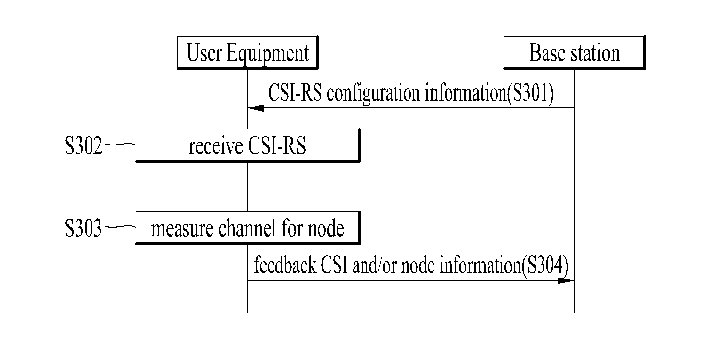
[0120]FIG. 3 is a flowchart of a method of transmitting a CSI-RS according to one embodiment of the present specification.

[0121]A base station transmits CSI-RS configuration inf...

2nd embodiment

2nd Embodiment

[0291]In the following description, a different embodiment proposed by the present specification is described. A method of transmitting control information to select (or determine) a valid node (or antenna node) in a distributed multi-node system is explained in detail. For clarity, a terminology ‘antenna node’ is only used in the following description.

[0292]First of all, a process of data transmission and reception between a base station and a user equipment in a DMNS (or DAS) shall be described.

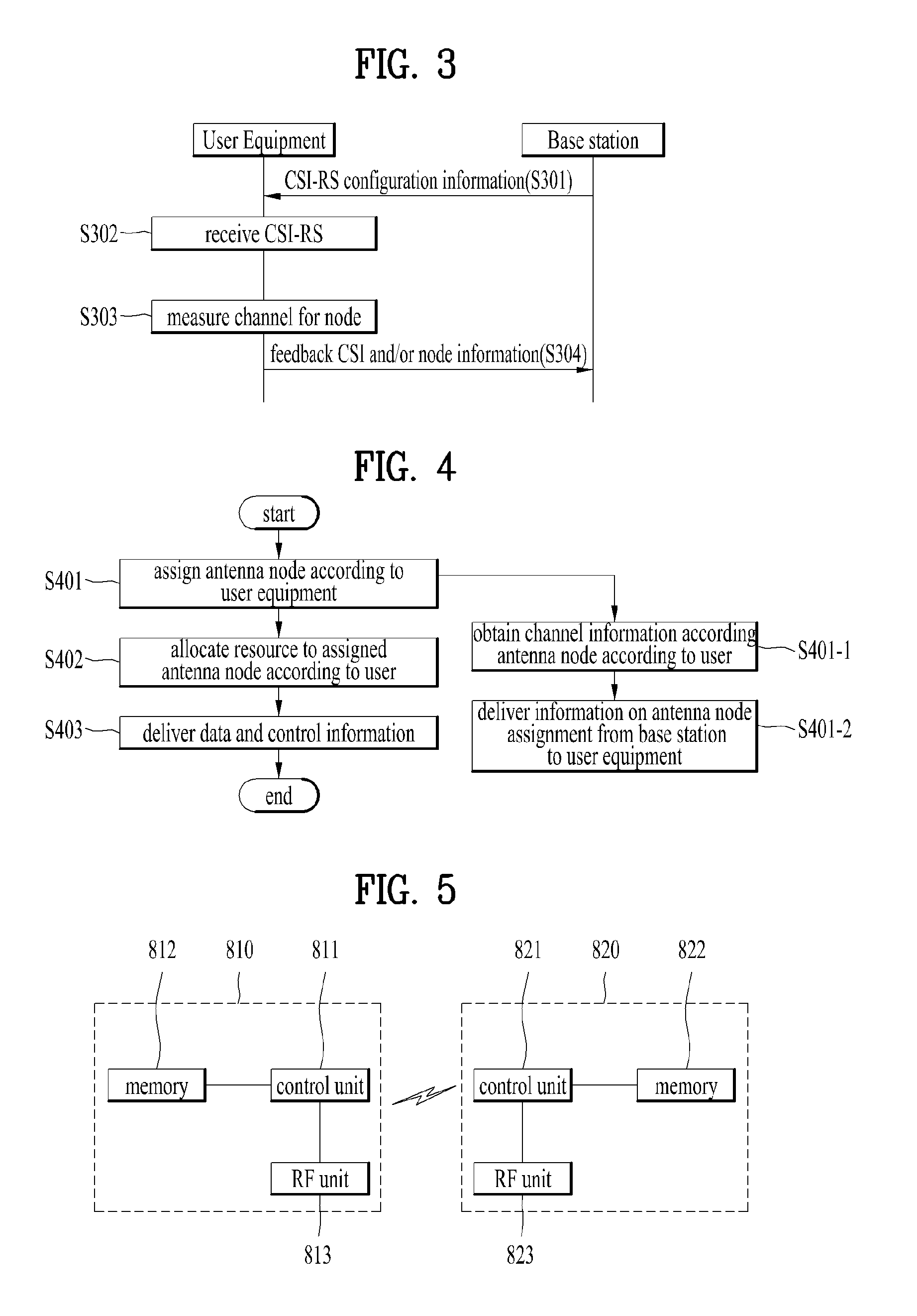
[0293]FIG. 4 is a flowchart of a process for transmitting and receiving data between a base station and a user equipment in a DMNS (distributed multi-node system).

[0294]Referring to FIG. 4, the process for transmitting and receiving data between a base station and a user equipment in a DMNS mainly consists of such a repetitive process as (1) antenna node assignment according to UE [S402], (2) resource allocation to the assigned antenna node according to a user [S402], and (3) ...


PUM


Abstract

The present invention relates to a method for transmitting a reference signal (RS) in a distributed multi-node system. The transmission method comprises: a step of constructing multiple channel state information reference signals (CSI-RSs) having power which is not zero in an intra-cell; and a step in which a base station transmits control information on the multiple CSI-RSs to a terminal. Here, the channel state information reference signals of multiple patterns may be transmitted in one subframe. The transmission method may further comprise a step of receiving feedback information on the channel state information reference signals from the terminal.

Description

TECHNICAL FIELD[0001]The present specification relates to a distributed multi-node system, and more particularly, to a channel measurement for a node (or an antenna node) and a method of determining a valid node.BACKGROUND ART[0002]Since a machine-to-machine (M2M) communication and such various devices requiring high data throughput as a smartphone, a tablet PC, and the like have emerged and are disseminated in a current wireless communication environment, data demand for a cellular network is rapidly increasing.[0003]In order to keep up with the high data demand, a communication technology has been developed with a carrier aggregation technology designed to efficiently use far more frequency bands, a cognitive radio technology, a multi antenna technology designed to increase data capacity in a limited frequency, a multi base station cooperation technology, and the like. And, the communication environment is evolved to a direction that density of a node, which is accessible in the v...

Claims


Application Information

Patent Timeline
Patent Type & Authority Applications(United States)
IPC IPC(8): H04W72/04
CPCH04W72/042H04B7/024H04L5/001H04L1/0031H04B7/0632H04W72/23
Inventor PARK, SUNGHOCHUN, JINYOUNGKIM, KITAE
Owner LG ELECTRONICS INC
Why Eureka
Try Eureka