Method and system for providing a shared demarcation point to monitor network performance

a network performance and demarcation point technology, applied in the field of shared demarcation point monitor network performance, can solve the problems of network troubleshooting becoming problematic, approach may not have a clear demarcation point between client signals, and short-reach optics are more expensive than long-reach optics

Inactive Publication Date: 2013-11-28
VERIZON PATENT & LICENSING INC
View PDF18 Cites 19 Cited by
  • Summary
  • Abstract
  • Description
  • Claims
  • Application Information

AI Technical Summary

Problems solved by technology

However, short-reach optics are more expensive than long-reach optics, especially at higher transport speeds.
However, the second approach may not have a clear demarcation point between the client signal a

Method used


Image

  • Method and system for providing a shared demarcation point to monitor network performance
  • Method and system for providing a shared demarcation point to monitor network performance
  • Method and system for providing a shared demarcation point to monitor network performance

Examples


Embodiment Construction

[0019]An apparatus, method, and software for providing a shared demarcation point, is described. In the following description, for the purposes of explanation, numerous specific details are set forth in order to provide a thorough understanding of the present invention. It is apparent, however, to one skilled in the art that the present invention may be practiced without these specific details or with an equivalent arrangement. In other instances, well-known structures and devices are shown in block diagram form in order to avoid unnecessarily obscuring the present invention.

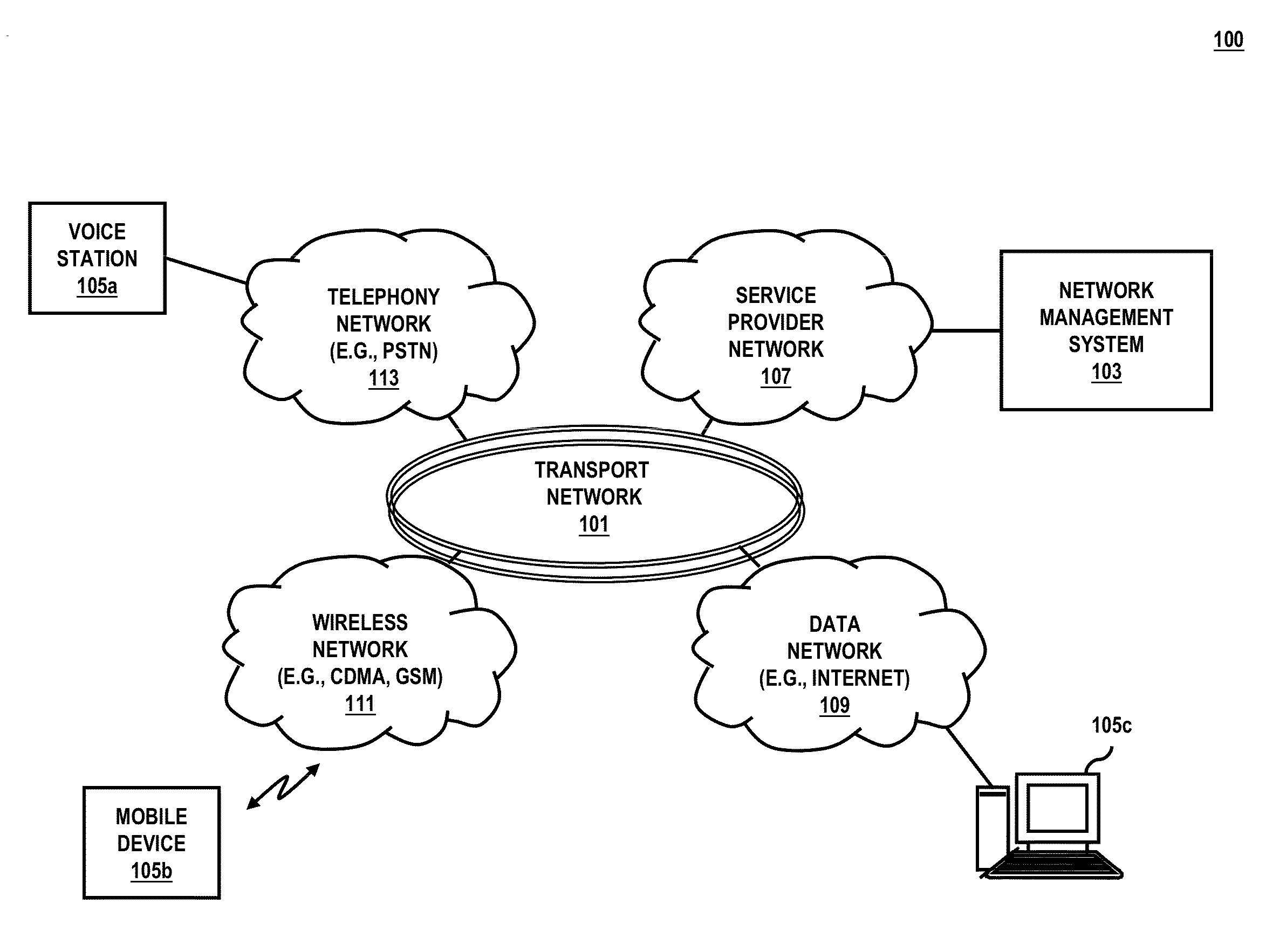
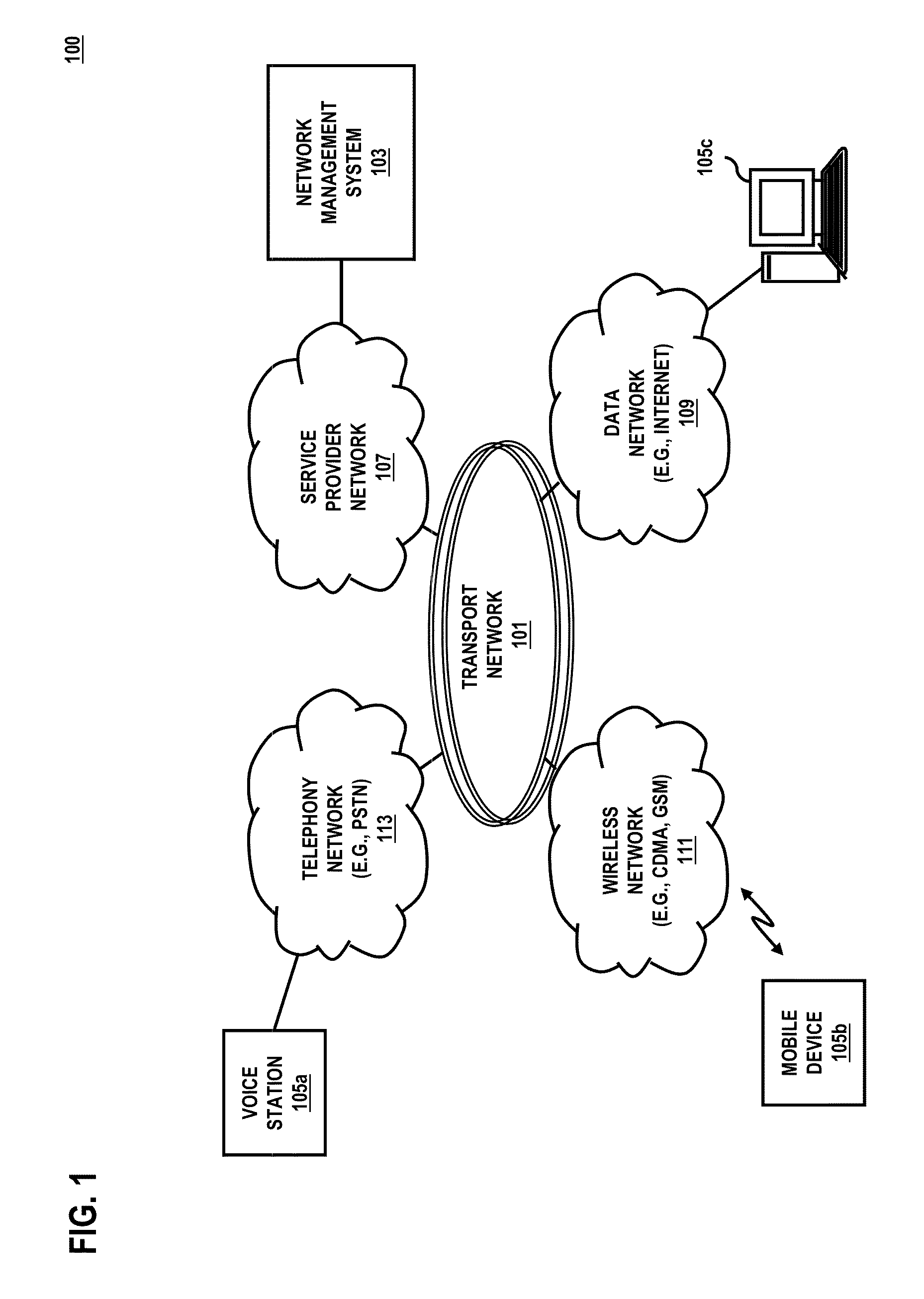
[0020]FIG. 1 is a diagram of a system 100 capable of providing a shared demarcation point within a transport network connected to a routing network using long-reach optics, according to one embodiment. As discussed above, there are generally two approaches for sending router traffic from end to end in a fiber optic transport network. The first approach uses short-reach optics to connect a router port at the user...


PUM


Abstract

An approach for detecting an error associated with a routing network coupled to a transport network comprising a plurality of optical communication nodes, switching, by an optical communication node, to a troubleshooting channel associated with the transport network using one or more router counterpart cards, and troubleshooting the error using the one or more router counterpart cards.

Description

BACKGROUND INFORMATION[0001]In general, connectivity between a routing network and an optical transport network is provided in one of two ways. Under a first approach, short-reach optics are used to connect a router port at a user (or client) side of a transponder to the client side router. Long-reach optics are then used to connect the transport network to the line side of the transponder. Under this approach, the transponder provides a clear demarcation point for a service provider to troubleshoot errors and / or network performance issues. However, short-reach optics are more expensive than long-reach optics, especially at higher transport speeds. Accordingly, a second approach has been developed that uses long-reach optics to connect the router port at the client side directly to the transport network. Because the second approach does not use short-reach optics, the cost associated with the second approach is less than the first approach. However, the second approach may not have ...

Claims


Application Information

Patent Timeline
IPC IPC(8): H04B10/08H04B10/00
CPCH04Q11/0001H04J14/0204H04J14/0205H04J14/0212H04J14/0267H04Q11/0062H04Q2011/0073
Inventor XIA, TIEJUN J.WELLBROCK, GLENN A.
Owner VERIZON PATENT & LICENSING INC
Why Eureka
Try Eureka