Low-level laser therapy

a low-level laser and laser therapy technology, applied in the field of tissue modulation systems, can solve the problems of compromising selectivity of electric neural modulation, challenging the use of this technique in portable or implantable neuromodulation devices, etc., and achieve the effect of reducing the excitability and reducing the excitability of the first nerve fiber

Inactive Publication Date: 2013-11-28
BOSTON SCI NEUROMODULATION CORP
View PDF13 Cites 29 Cited by
  • Summary
  • Abstract
  • Description
  • Claims
  • Application Information

AI Technical Summary

Benefits of technology

[0010]In accordance with a first aspect of the present inventions, a method of treating a patient with an ailment using an optical element implanted within the patient is provided. The method comprises conveying low-level laser energy having a wavelength in the range of 600 nm-2500 nm from the optical element to a neuronal element of the patient, thereby modulating the neuronal element to treat the ailment. The low-level laser energy may decrease the excitability of the neuronal element (e.g., if the wavelength is in the range of 600 nm-1200 nm, and preferably in the range of 600 nm-900 nm) or increase the excitability of the neuronal element (e.g., if the wavelength is in the range of 1400-2500 nm).
[0016]In accordance with a third aspect of the present inventions, a method of treating a patient with an ailment. The method comprises conveying electrical energy to a first neuronal element, thereby modulating the first neuronal element, and conveying low-level laser energy having a wavelength in the range of 600 nm-2500 nm to the first neuronal element, thereby modulating the first neuronal element. At least one of the conveyance of the electrical energy and the conveyance of the low-level laser energy treats the ailment. The low-level laser energy may decrease the excitability of the neuronal element (e.g., if the wavelength is in the range of 600 nm-1200 nm, and preferably in the range of 600 nm-900 nm) or increase the excitability of the neuronal element (e.g., if the wavelength is in the range of 1400-2500 nm).
[0019]In still another method, the electrical energy is conveyed to a first target site along a plurality of neuronal elements that includes the first neuronal element, thereby decreasing the excitability of the plurality of neuronal elements at the first target site, while the low-level laser energy is conveyed at a second target site to a portion of the plurality of neuronal elements that includes the first neuronal element, thereby increasing the excitability of the portion of the plurality of neuronal elements at the second target site, such that only a portion of action potentials intrinsically generated respectively in the plurality of neuronal elements proximal to the first target site is conveyed along the plurality of neuronal elements distal to the second target site.
[0020]In yet another method, the electrical energy is conveyed to a first target site along a plurality of neuronal elements that includes the first neuronal element, thereby increasing the excitability of the plurality of neuronal elements at the first target site, while the low-level laser energy is conveyed at a second target site to a portion of the plurality of neuronal elements that includes the first neuronal element, thereby decreasing the excitability of the portion of the plurality of neuronal elements at the second target site, such that only a portion of action potentials intrinsically generated respectively in the plurality of neuronal elements proximal to the first target site is conveyed along the plurality of neuronal elements distal to the second target site.
[0021]In yet another method, the electrical energy is conveyed to the first neuronal element at a first target site, thereby bi-directionally evoking action potentials in the first neuronal element, while the low-level laser energy is conveyed to the first neuronal element at a second target site, thereby decreasing the excitability of the first neuronal element at the second target site, such that the action potentials are blocked at the second target site.

Problems solved by technology

However, there are safety concerns with electrical neural modulation due to electro-chemical reaction at the tissue-electrode interface.
Furthermore, electrical neural modulation may compromise selectivity due to the spread of current.
However, the generation of pulsed optical energy for direct neuron stimulation may call for a powerful laser driver and complicated system to provide an optical path, thus making it challenging to use this technique in portable or implantable neuromodulation devices.

Method used


Image

  • Low-level laser therapy
  • Low-level laser therapy
  • Low-level laser therapy

Examples


Embodiment Construction

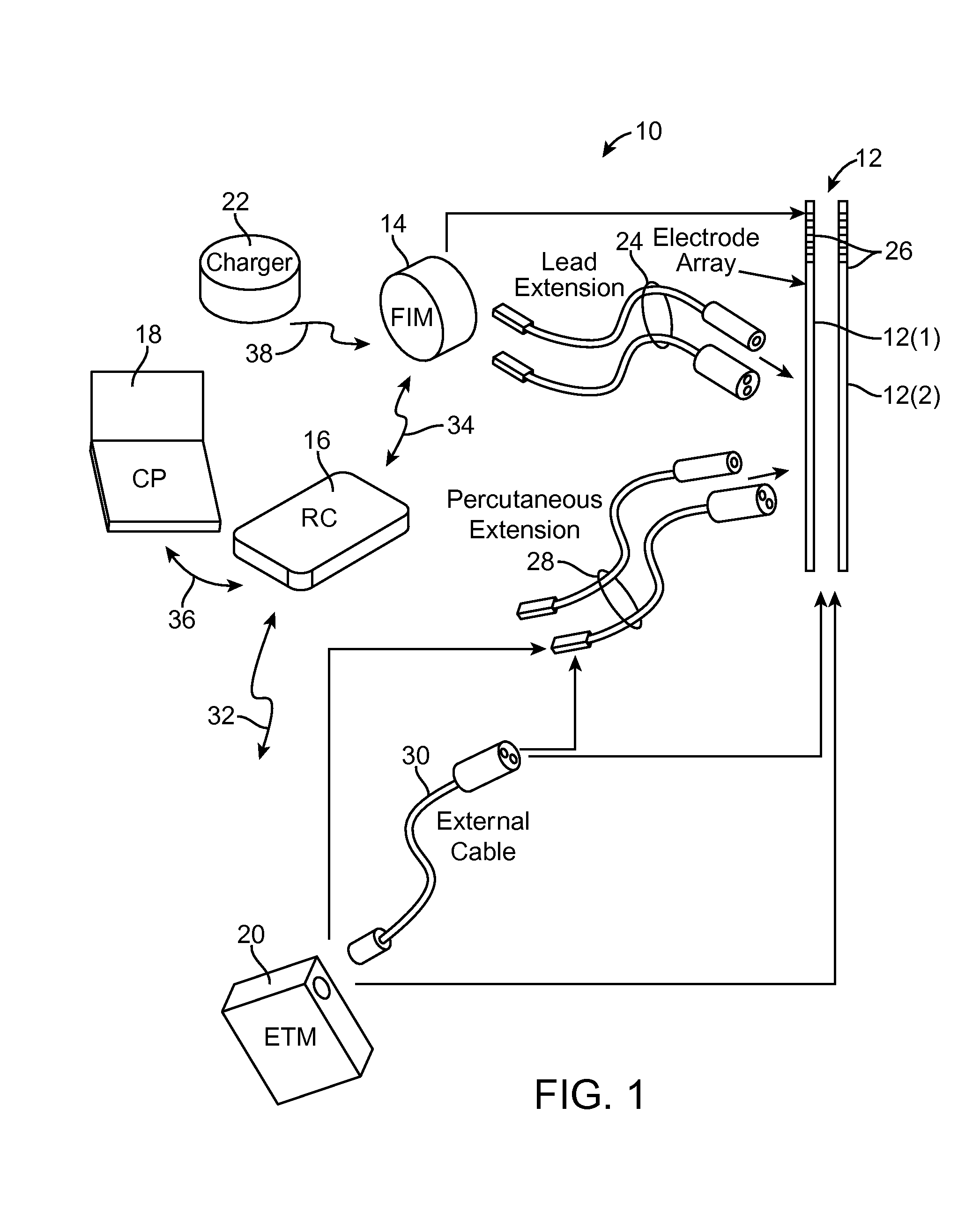
[0063]Turning first to FIG. 1, an exemplary neuromodulation system 10 is used to treat any one of a variety of ailments using low-level laser energy, and in some cases, a combination of the laser energy and electrical energy to treat any of the ailments, as well as to prevent or minimize any side-effects.

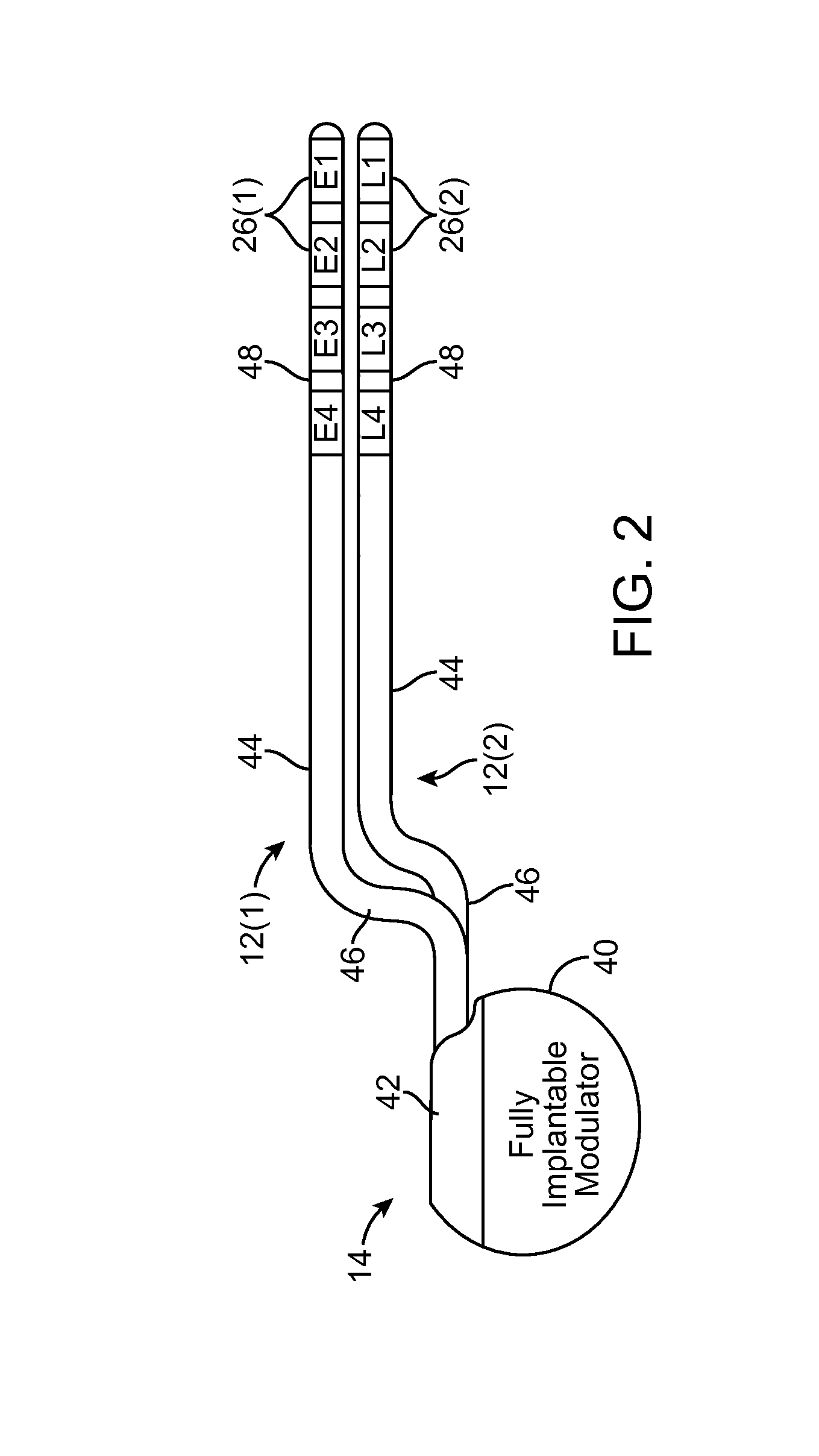
[0064]The system 10 generally includes a plurality of implantable neuromodulation leads 12, a fully implantable modulator (FIM) 14, an external control device in the form of a remote controller RC 16, a clinician's programmer (CP) 18, an external trial stimulator (ETS) 20, and an external charger 22.

[0065]The FIM 14 is physically connected via one or more lead extensions 24 to the neuromodulation leads 12, which carry a plurality of neuromodulation elements 26. Although twp neuromodulation leads 12 are illustrated, it should be appreciated that less or more neuromodulation leads 12 can be provided. As will be described in further detail below, the FIM 14 includes circuitry that deli...


PUM


Abstract

A method of treating a patient with an ailment using an optical element implanted within the patient, comprising conveying low-level laser energy having a wavelength in the range of 600 nm-2500 nm from the optical element to a neuronal element of the patient, thereby modulating the neuronal element to treat the ailment.

Description

RELATED APPLICATION DATA[0001]The present application claims the benefit under 35 U.S.C. §119 to U.S. provisional patent application Ser. No. 61 / 652,093, filed May 25, 2012. The foregoing application is hereby incorporated by reference into the present application in its entirety.FIELD OF THE INVENTION[0002]The present invention relates to tissue modulation systems, and more particularly, to a system and method for therapeutically modulating nerve fibers.BACKGROUND OF THE INVENTION[0003]Among many techniques attempted for neurostimulation (e.g., electrical, chemical, mechanical, thermal, magnetic, optical, and so forth), electrical stimulation is the standard and most common technique. Implantable electrical stimulation systems have proven therapeutic in a wide variety of diseases and disorders. Pacemakers and Implantable Cardiac Defibrillators (ICDs) have proven highly effective in the treatment of a number of cardiac conditions (e.g., arrhythmias). Spinal Cord Stimulation (SCS) te...

Claims


Application Information

Patent Timeline
Patent Type & Authority Applications(United States)
IPC IPC(8): A61N5/06
CPCA61N5/0622A61N1/0551A61N2005/063A61N2005/0645A61N2005/0651A61N2005/0659A61N2005/0662A61N1/0534A61N1/3605A61N2005/0652
Inventor ZHU, CHANGFANGLEE, DONGCHULBRADLEY, KERRY
Owner BOSTON SCI NEUROMODULATION CORP
Why Eureka
Try Eureka