
Femoral extension prosthetic component and tibial shelf prosthetic component for unicondylar meniscal bearing knee prosthesis and prosthesis including such a component

a technology of femoral extension and prosthesis, which is applied in the field of femoral extension prosthesis and tibial shelf prosthesis components for unicondylar meniscal bearing knee prosthesis and prosthesis, can solve the problems of bone-on-bone contact and pain, no drug treatment has been found to reverse these processes, and the articular surface or ligament damage changes, etc., to achieve the effect of sufficient rigidity

Active Publication Date: 2013-11-28
BIOMET UK +4
View PDF4 Cites 14 Cited by
  • Summary
  • Abstract
  • Description
  • Claims
  • Application Information

AI Technical Summary

Benefits of technology

The invention provides methods for reducing the gap between the inner edges of the femoral and tibial components to prevent partial dislocation. This can improve the stability and reliability of knee joint replacements.

Problems solved by technology

Damage to the articular surfaces or to the ligaments changes the patterns of movement of the bones on each other and the response of the joint to load.
Osteoarthritis follows from failure of the cartilage in one or other of the three joints, leading to bone-on-bone contact and the onset of pain.
No drug treatment has been found which reverses these processes.
Partial knee replacement is surgically more demanding and is not always used when it is indicated.
Care has to be taken not to overstuff the joint, leading to pain and failure of the components and, in the case of a partial knee replacement, degeneration of the preserved compartments.
A complication of mobile bearing arthroplasty is dislocation of the bearing.
However, if too thick a bearing is selected, there is a risk of overstuffing the joint, which can lead to pain and failure of the components and, in the case of a partial knee replacement, degeneration of the preserved compartments.
Nonetheless, lateral bearing dislocation continues to be a problem.
Partial medial dislocation and complete lateral dislocation continue to be a problem in lateral arthroplasty.

Method used


Image

  • Femoral extension prosthetic component and tibial shelf prosthetic component for unicondylar meniscal bearing knee prosthesis and prosthesis including such a component
  • Femoral extension prosthetic component and tibial shelf prosthetic component for unicondylar meniscal bearing knee prosthesis and prosthesis including such a component
  • Femoral extension prosthetic component and tibial shelf prosthetic component for unicondylar meniscal bearing knee prosthesis and prosthesis including such a component

Examples


first embodiment

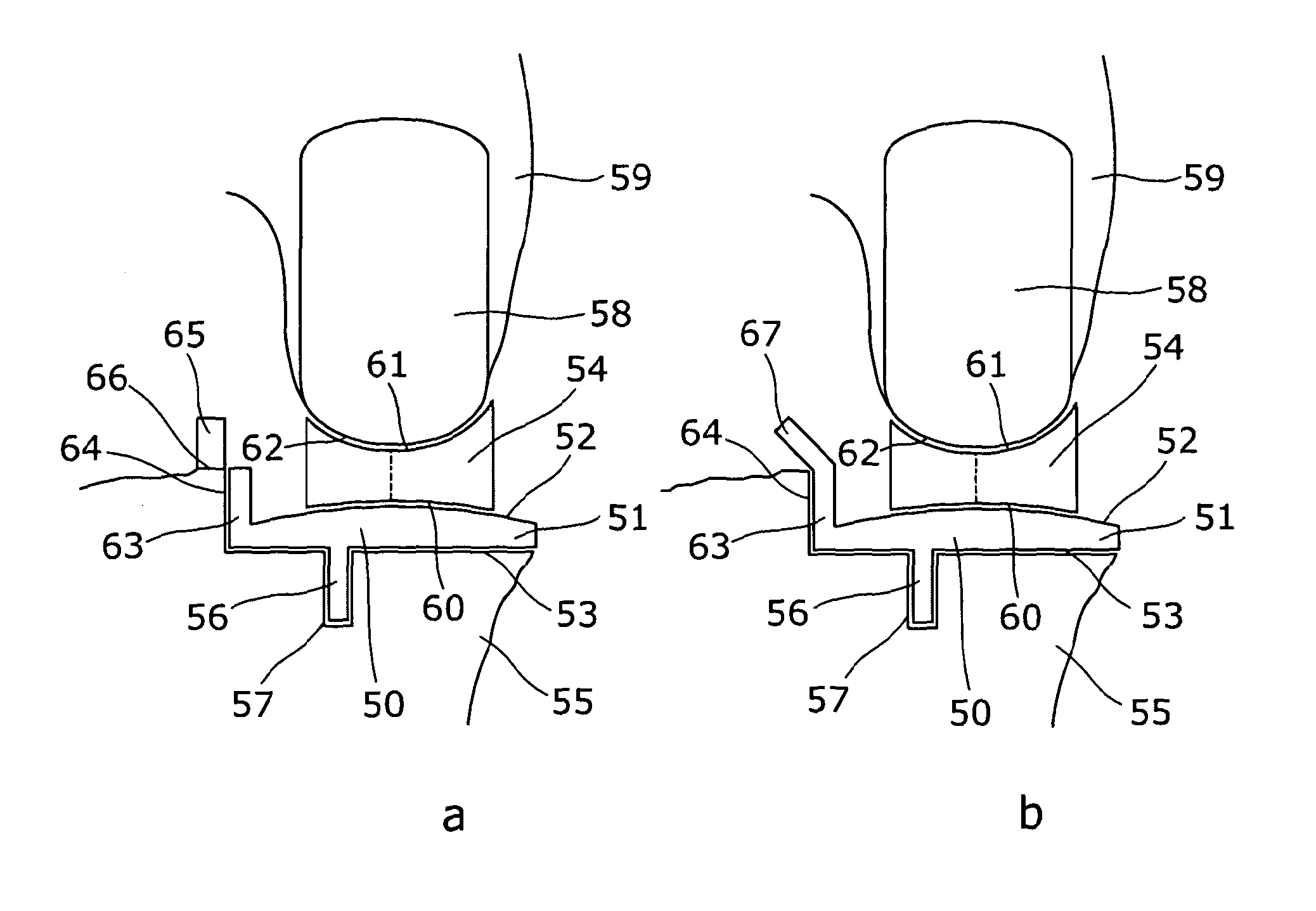
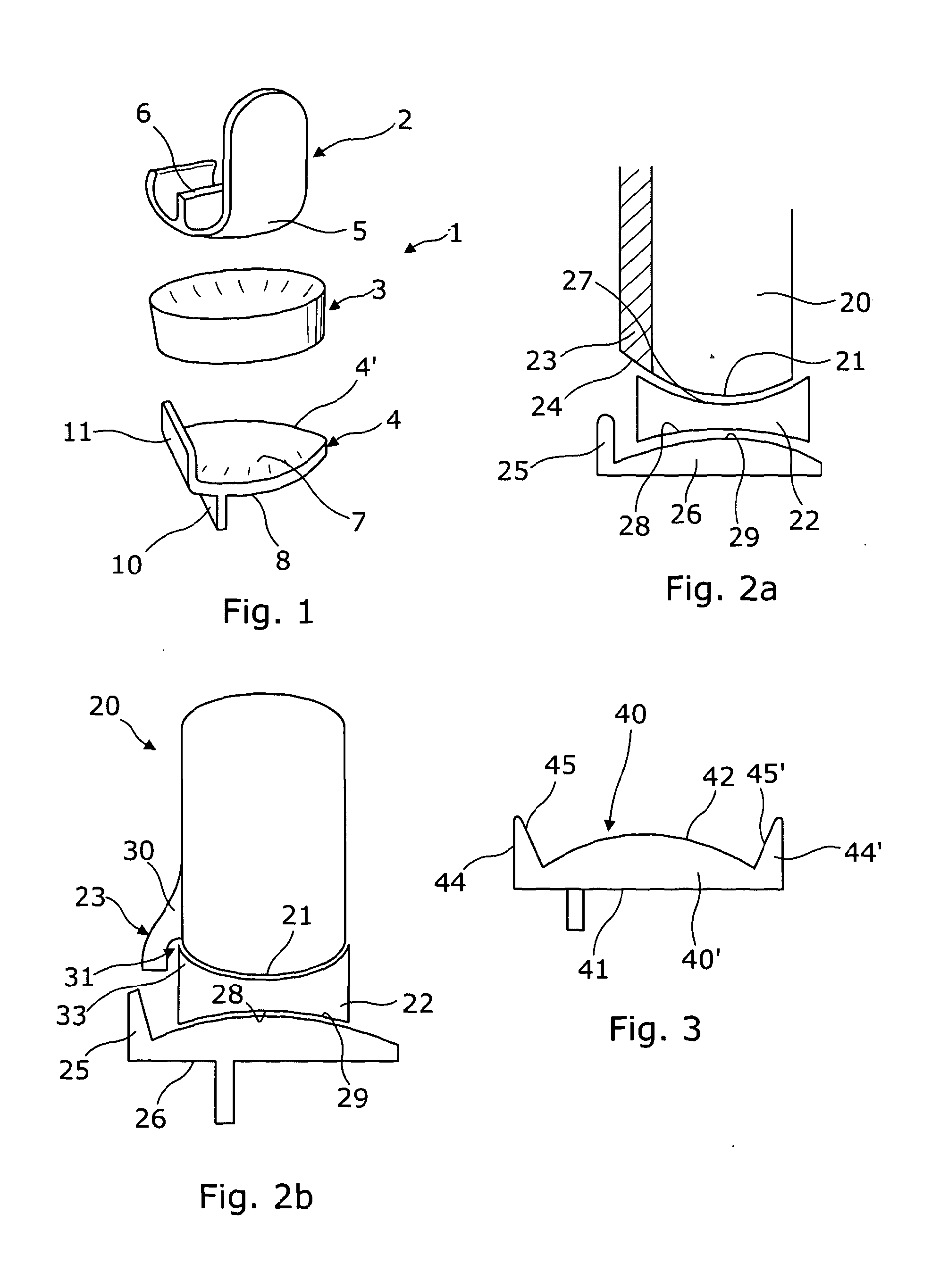
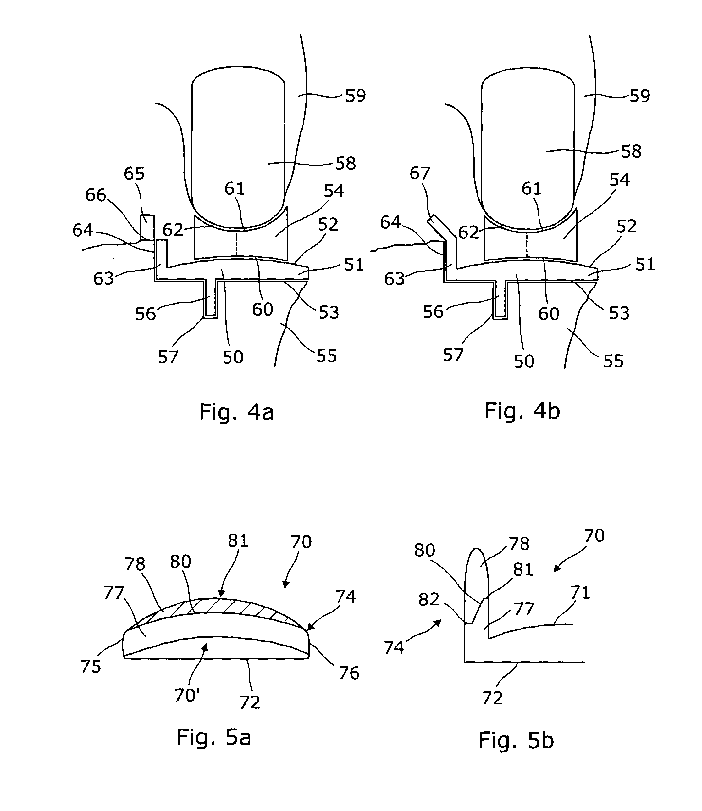
[0140]FIG. 8a shows the seventh aspect of the invention. The tibial component 140 has a tibial shelf 140′ which is substantially D-shaped in plan view, having a bearing surface 141 on one side and a connection surface 142 on an opposed side. The connection surface 142 includes a securing element 143. The bearing surface 141 includes an inner wall, in this case medial wall 144, that extends axially from the periphery thereof. The medial wall 144 extends around approximately a third of the perimeter of the bearing surface 141. In this embodiment, the bearing surface 141 is curved in the medial-lateral direction only and thus appears barrel shaped, with the axis of the barrel extending in the anterior-posterior direction. The peak of the ridge formed by the curved surface thus extends in the anterior-posterior direction and is shown by dashed line 145. The bearing surface 141 is substantially flat in the anterior-posterior direction. In this embodiment, the peak of the ridge 145 extend...

second embodiment

[0141]FIG. 8b shows the seventh aspect of the invention. The same reference numerals have been used for the same features as those shown in FIG. 8a. This embodiment differs from that of FIG. 8a as the bearing surface 141 is not curved in medial-lateral direction. Instead, it is curved in the anterior-posterior direction only. Thus, the bearing surface 141 is barrel shaped but with the axis of the barrel extending in the medial-lateral direction. The peak of the ridge formed by the curved surface thus extends in the medial-lateral direction and is shown by dashed line 146. The bearing surface 141 is substantially flat in the medial-lateral direction. In this embodiment, the peak of the ridge 146 extends through the centre of the bearing surface 141, but it could be offset to the anterior or posterior sides.

third embodiment

[0142]FIG. 8c shows the tibial component 140 of the seventh aspect of the invention. Once again the same reference numerals have been used for the same features as those shown in FIGS. 8a and 8b. In this embodiment, the bearing surface 141 has a first function of curvature in the anterior-posterior direction and a second function of curvature in the medial-lateral direction. Thus, the surface may be a quadric surface. The first function of curvature is different to the second function of curvature. It will be appreciated that the functions of curvature could be the same depending on the configuration of the knee replacement components. The ridge 127 of the anterior-posterior curve and the ridge 128 of the medial-lateral curve intersect at the centre of the bearing surface 141. It will be appreciated that the apex of the surface could be offset from the centre of the bearing surface 141.

[0143]FIG. 9 shows a diagrammatic anteroposterior view of a meniscal bearing 150 of the eighth asp...


PUM


Abstract

A femoral extension prosthetic component for use in a unicondylar meniscal bearing unicompartmental knee replacement is described. The femoral component comprises a securing element and a bearing surface, the securing element adapted to abut and be connected to a distal end of a femur bone, and the bearing surface adapted to abut a meniscal bearing. The femoral component includes an entrapment portion adapted to extend beyond the meniscal bearing. Tibial components and meniscal bearings are also described, as well as methods of using such components.

Description

CROSS-REFERENCE TO RELATED APPLICATION(S)[0001]The present application claims priority under 35 U.S.C. §365 to International Patent Application No. PCT / GB2011 / 051681 filed Sep. 8, 2011. International Patent Application No. PCT / GB2011 / 051681 claims priority under 35 U.S.C. §365 and / or 35 U.S.C. §119(a) to United Kingdom Patent Application No. 1015087.8 filed Sep. 10, 2010 which are incorporated herein by reference into the present disclosure as if fully set forth herein.[0002]This invention relates to a tibial shelf component for use in unicompartmental, unicondylar, meniscal bearing knee replacements. It also relates to a combination of a tibial component and meniscal bearing for use in such unicompartmental knee replacements. It also relates to a femoral prosthetic component for use in unicompartmental, unicondylar, meniscal bearing knee replacement. It also relates to a method of performing knee arthroplasty.BACKGROUND OF THE INVENTION[0003]The knee comprises three inter-dependent...

Claims


Application Information

Patent Timeline
IPC IPC(8): A61F2/46A61F2/38
CPCA61F2/461A61F2/389A61F2/3859A61F2/3868A61F2002/30224A61F2002/30245A61F2002/30403A61F2002/30662A61F2002/30934A61F2002/3895A61F2/30A61F2/38
Inventor GOODFELLOW, JOHN WILLIAMO'CONNOR, JOHNDODD, CHRIS ALEXANDERMURRAY
Owner BIOMET UK
Learn More