Unmanned autonomous operating system
a technology of autonomous operating system and operating system, which is applied in the direction of process and machine control, distance measurement, instruments, etc., can solve the problems of difficulty in recognizing each of the operating areas, insufficient area recognition accuracy, and intensity of received signals
- Summary
- Abstract
- Description
- Claims
- Application Information
AI Technical Summary
Benefits of technology
Problems solved by technology
Method used
Image
Examples
first embodiment
[0033]An unmanned autonomous operating system according to the present invention will now be explained with reference to the attached drawings.
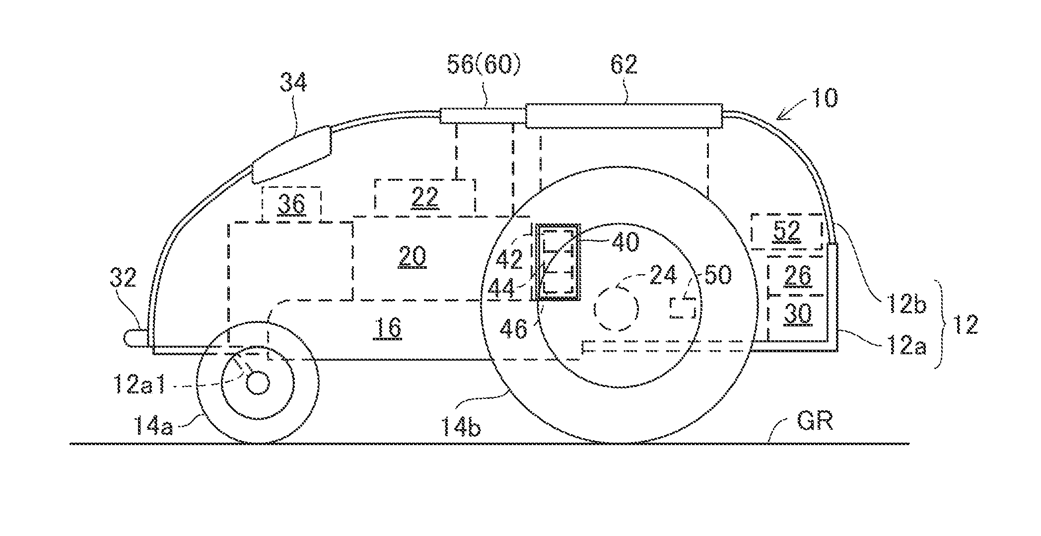
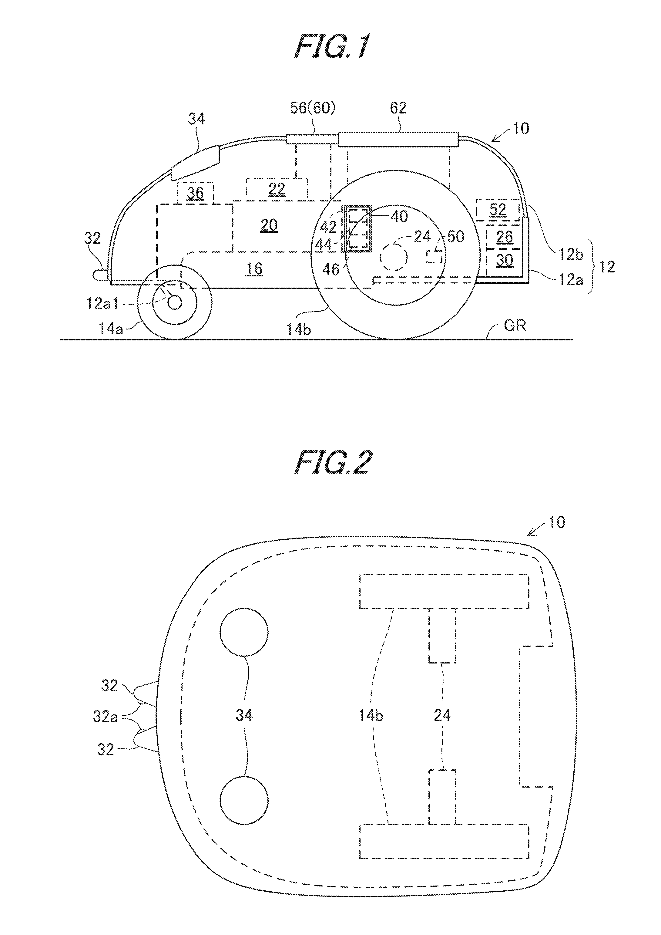
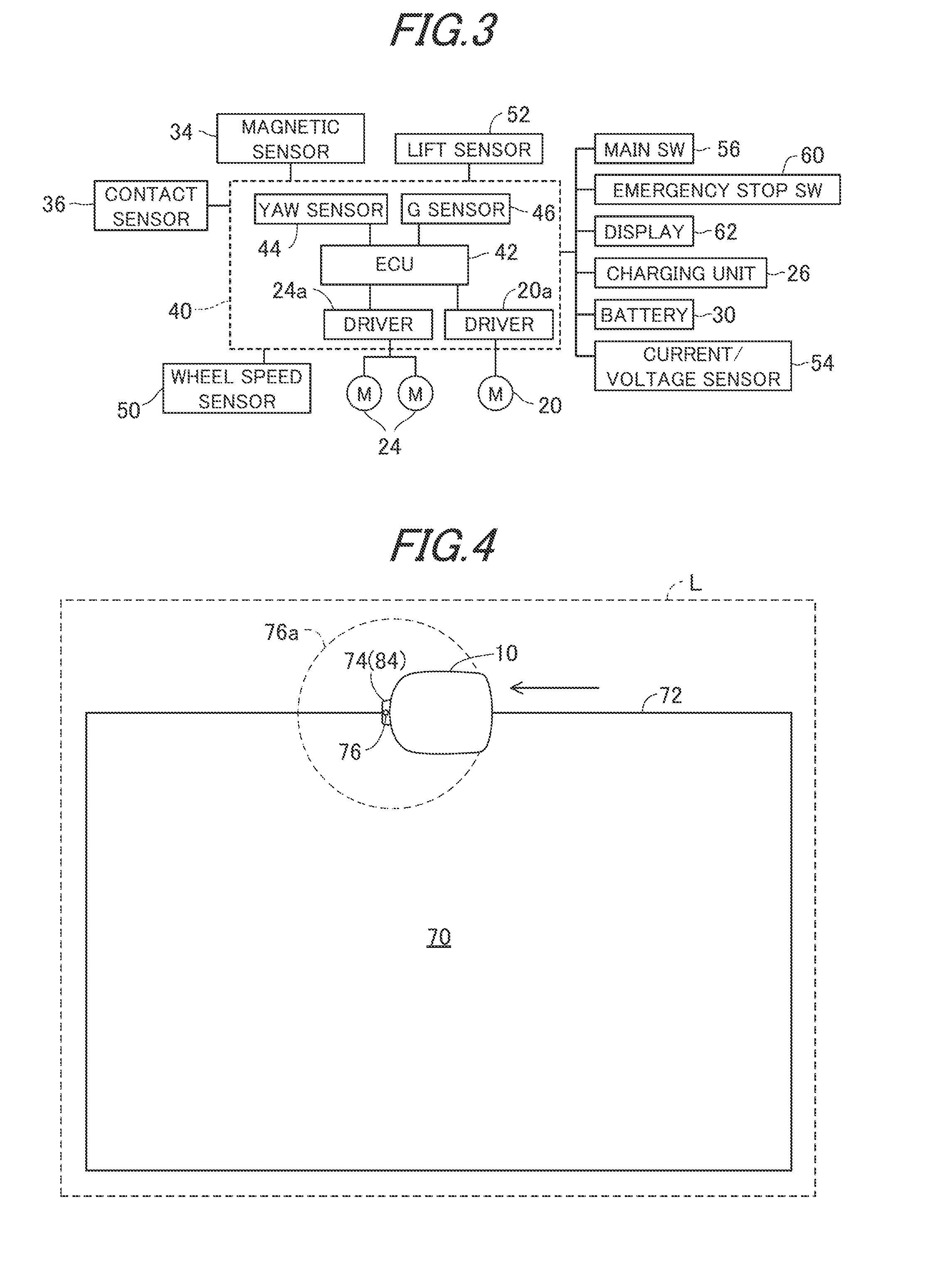
[0034]FIG. 1 is a side view of an unmanned autonomous operating system according to a first embodiment of the invention, FIG. 2 is a plan view of the vehicle shown in FIG. 1, FIG. 3 is a block diagram showing input and output of devices mounted on the vehicle shown in FIG. 1, FIG. 4 is a plan view showing an operating area where a station (charge station) is installed, FIG. 5 is block diagram showing the configuration of the station, FIG. 6 is an explanatory view showing a charging process at the station, FIG. 7 is an explanatory view showing a magnetic field generated in an area wire embedded in the operating area shown in FIG. 4.
[0035]In the figures symbol 10 indicates an unmanned autonomous operating vehicle. The vehicle 10 has a vehicle body 12 and wheels 14. The body 12 includes a chassis 12a and a frame 12b attached to the chassis 12a, ...
second embodiment
[0104]FIG. 15 is a flowchart showing the operation of the unmanned autonomous operating system according the invention, particularly to the operation of the area signal registration by the type number at the side of the vehicle 10 prior to the lawn mower operation. The illustrated program is executed by the ECU 42 at every predetermined time intervals.
[0105]Explaining this, the program starts processing when the main switch 56 is turned on by the user in S300, and proceeds to S302, in which the user is urged to input the PIN code through the input of the menu screen on the display 62. When the PIN code is inputted and it is determined to be authentic, a display “Searching signal” is made on the display 62 in S304. This means that the recognition of the operating area 70 is in progress.
[0106]The program then proceeds to S306, in which the same type number of the area signal as that registered in the last time (time before the main switch 56 was turned off), for example, the area sign...
third embodiment
[0117]FIG. 18 is a flowchart showing the operation of the unmanned autonomous operating system according to the invention, particularly to the operation of the vehicle 10a under a situation where there may exist an interference with other area signal. The illustrated program is executed by the ECU 42 at every predetermined time intervals.
[0118]Explaining this, the lawn mower operation is started in S400 and the program proceeds to S402, in which operation of the running motor 24 is controlled to make the vehicle 10 to run, and to S404, in which the intensity of the area signal is detected.
[0119]The program then proceeds to S406, in which it is determined whether the intensity of the area signal detected at this program loop changes greatly relative to that detected at the preceding (last) program loop.
[0120]When the result is negative, since this indicates that no interference occurs, the program proceeds to S408, in which it is determined whether the vehicle 10 is outside of the op...
PUM
 Abstract
Description
Claims
Application Information
 - R&D
- Intellectual Property
- Life Sciences
- Materials
- Tech Scout
- Unparalleled Data Quality
- Higher Quality Content
- 60% Fewer Hallucinations
Browse by: Latest US Patents, China's latest patents, Technical Efficacy Thesaurus, Application Domain, Technology Topic, Popular Technical Reports.
© 2025 PatSnap. All rights reserved.Legal|Privacy policy|Modern Slavery Act Transparency Statement|Sitemap|About US| Contact US: help@patsnap.com


