Wheel loader

a technology of loader and wheel, applied in the direction of vehicle position/course/altitude control, process and machine control, instruments, etc., to achieve the effect of high work efficiency

Active Publication Date: 2013-11-28
NIHON KENKI CO LTD
View PDF2 Cites 25 Cited by
  • Summary
  • Abstract
  • Description
  • Claims
  • Application Information

AI Technical Summary

Benefits of technology

[0010]The present invention allows a hybrid wheel loader including an electrified travel drive portion to maintain high work efficiency even when an output upper limit of a hybrid system falls short of a power requirement required by the vehicle due to, for example, discharge of an electrical storage device.

Problems solved by technology

In addition, the wheel loader repeatedly performs a traveling operation involving frequent starts and stops during working.

Method used


Image

  • Wheel loader
  • Wheel loader
  • Wheel loader

Examples


Embodiment Construction

[0021]An embodiment of the present invention will be described below with reference to the accompanying drawings.

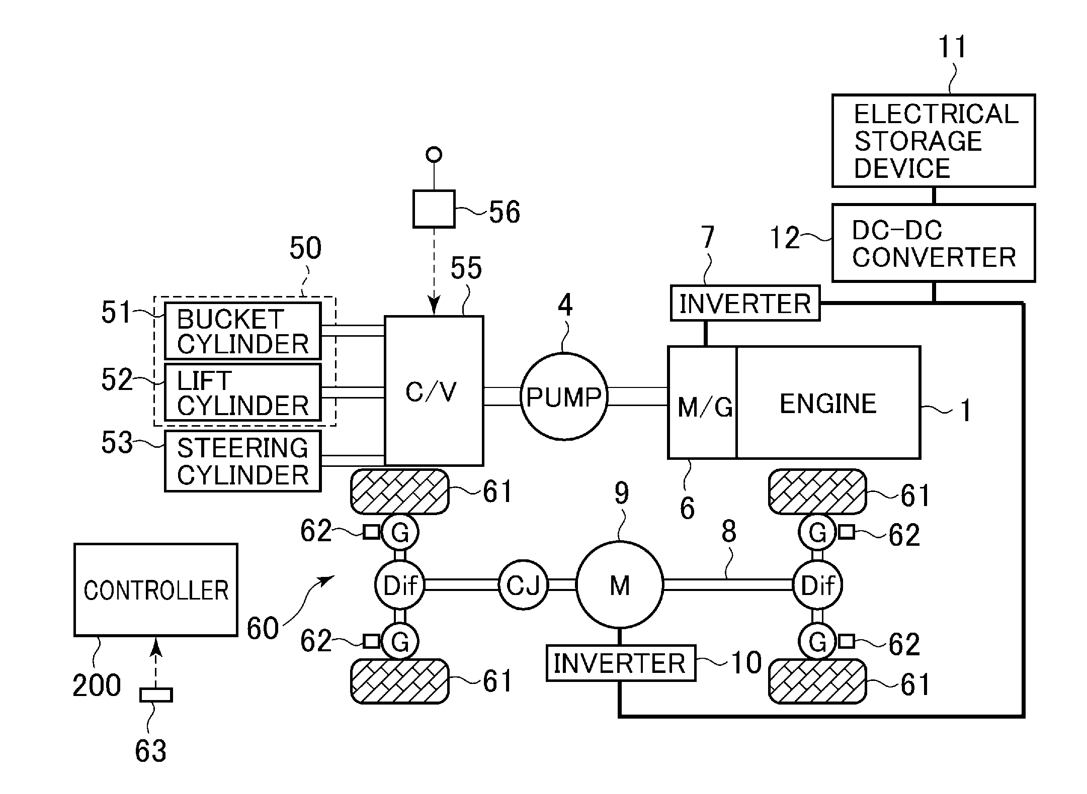
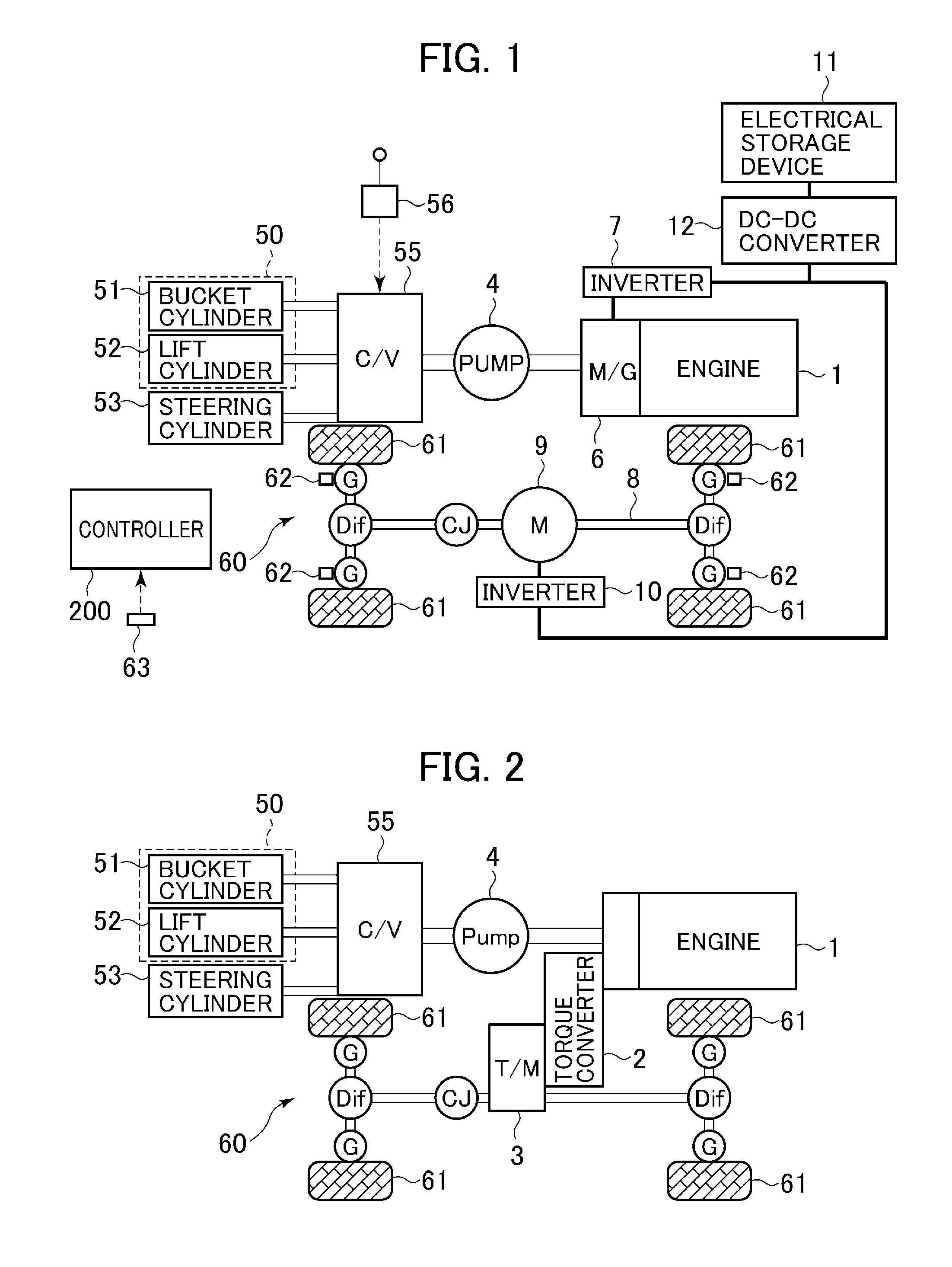
[0022]FIG. 1 is a system configuration diagram showing a hybrid wheel loader according to the embodiment of the present invention. The wheel loader shown in this figure includes an engine 1, a motor generator (motor / generator (M / G)) 6, an inverter 7, a hydraulic pump 4, a work implement 50, hydraulic actuators (a bucket cylinder 51, a lift cylinder 52, and a steering cylinder 53), a track structure 60, a travel electric motor 9, an inverter 10, an electrical storage device 11, operating devices (a control lever 56 and a steering wheel (not shown)), and a controller 200. Specifically, the motor generator 6 is connected to an output shaft of the engine 1. The inverter 7 controls the motor generator 6. The hydraulic pump 4 is connected to a rotational shaft of the motor generator 6. The work implement 50 includes a bucket and a lift arm (not shown) and is mounted forwardly o...


PUM


Abstract

A hybrid wheel loader is provided, the hybrid wheel loader achieving high work efficiency even with a short supply of power to be output relative to a vehicle power requirement.
The hybrid wheel loader includes a motor generator 6 connected to an engine (1), a hydraulic pump (4) connected to the motor generator, a hydraulic actuator (51, 52, 53) driven by hydraulic oil supplied from the hydraulic pump, a travel electric motor (9) for driving wheels (61), and an electrical storage device (11) connected to each of the motor generator and the electrical storage device via respective inverters (7, 10). When a total requirement power value is greater than a hybrid output upper limit value, either one of a hydraulic requirement power value Pf and a travel requirement power value Prun is limited according to an operation of the wheel loader to thereby set the total requirement power value to a value equal to, or less than, the hybrid output upper limit value.

Description

TECHNICAL FIELD[0001]The present invention relates to a wheel loader including an engine and an electrical storage device as power sources.BACKGROUND ART[0002]In recent years, industrial products are more and more oriented toward energy saving from the viewpoints of, for example, environmental issues and soaring crude oil prices. This trend is also true with the field of construction and work vehicles that have so far mainly used hydraulic drive systems operated by diesel engines. Many of these vehicles are increasingly electrified to yield higher efficiency and consume less amounts of energy. For example, if the drive parts of the abovementioned construction and work vehicles are electrified, specifically, if electric motors are used for their drive sources, a number of energy-saving effects can be expected, such as driving of engines with high efficiency (for a hybrid model), improved power transmission efficiency, and recovery of regenerative electricity, in addition to reduced a...

Claims


Application Information

Patent Timeline
Patent Type & Authority Applications(United States)
IPC IPC(8): E02F9/20
CPCE02F9/2075Y10S903/93E02F9/2079E02F9/2235B60W50/087B60W10/06B60W10/08B60W10/30B60W30/18B60W2300/121E02F9/2296B60K6/46B60W20/15Y02T10/62E02F9/22E02F9/20
Inventor KANEKO, SATORUIKIMI, TAKASHIMORIKI, HIDEKAZUITO, NORITAKAYANAGIMOTO, HIROAKI
Owner NIHON KENKI CO LTD
Why Eureka
Try Eureka