Cutting chain for cutting mineral and metal materials

a technology of cutting chain and cutting element, applied in the direction of saw chain, saw blade, manufacturing tool, etc., can solve the problem that the cutting chain cannot be opened, and achieve the effect of high stability and secure fixing of the cutting element, and preventing damage to the cutting elemen

a technology of cutting chain and cutting element, applied in the direction of saw chain, saw blade, manufacturing tool, etc., can solve the problem that the cutting chain cannot be opened, and achieve the effect of high stability and secure fixing of the cutting element, and preventing damage to the cutting elemen

US20130319201A1Inactive Publication Date: 2013-12-05ANDREAS STIHL AG & CO KG

Image

  • Cutting chain for cutting mineral and metal materials
  • Cutting chain for cutting mineral and metal materials
  • Cutting chain for cutting mineral and metal materials

Examples


Embodiment Construction

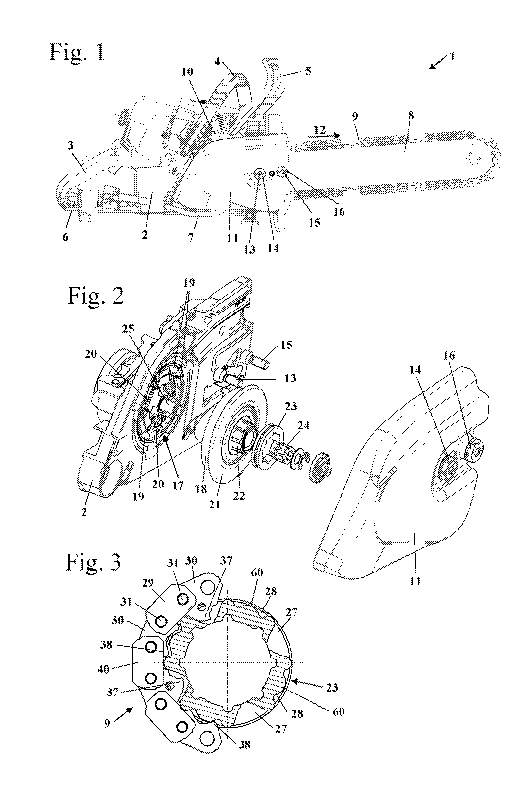
[0044]FIG. 1 shows a stone cutter 1 used for cutting mineral and metal materials such as concrete, for example. The stone cutter 1 has a housing 2 to which are fixed a rear handle 3 and a handlebar 4 for guiding the stone cutter 1 during operation. Fixed to the housing 2 is a guide bar 8 which projects forwards on the side of the housing 2 opposite the rear handle 3. Fitted around the circumference of the guide bar 8 is a cutting chain 9 which is driven around the guide bar 8 in a direction of travel 12 by a drive motor 10 positioned in the housing 2. In the embodiment the drive motor 10 takes the form of an internal combustion engine, in particular a two-stroke single cylinder engine. However, the drive motor may also be a four-stroke engine. The drive motor may also advantageously be an electric motor which is supplied with power by an electric cable or accumulator. A hand guard 5 which extends along the side of the handlebar 4 facing the guide bar 8 is fixed to the housing 2.

[004...


PUM

PropertyMeasurementUnit
Fractionaaaaaaaaaa
Fractionaaaaaaaaaa
Timeaaaaaaaaaa

Abstract

A cuffing chain for cutting mineral and metal materials has central chain links and lateral connecting links. The cutting chain has connecting pins with a central section which has a diameter that is greater than the diameter of openings in adjacent connecting links. The cutting chain has two connecting links which have a supporting section instead of a cutting element. At least two second connecting links positioned adjacent to one another at right angles to the direction of travel of the cutting chain are formed separately from one another. As a result, the cutting chain can be opened for maintenance and repairs despite the use of collar studs as connecting pins.

Description

BACKGROUND OF THE INVENTION[0001]The invention relates to a cutting chain for cutting mineral and metal materials. The cutting chain comprises central chain links which are connected to one another by lateral connecting links, at least two connecting links being positioned adjacent to one another at right angles to the direction of travel of the cutting chain, there being provided to connect the central chain links to the connecting links connecting pins which project through first openings in the connecting links and through second openings in the central chain links, each connecting pin having a central axis, said central axes lying in a central axis plane when the cutting chain is extended, the cutting chain having at least one first connecting link to which is fixed a cutting element that has a top facing away from the connecting pin, the cutting chain having at least one second connecting link that has a supporting section instead of a cutting element.[0002]A cutting chain for ...

Claims


Application Information

Patent Timeline
05 Dec 2013
Publication
US20130319201A1
IPC
B23D61/12; B28D1/08
CPC
B27B33/14; B27B33/141; B28D1/124; B27B33/147; Y10T83/909; B23D57/02
Inventors
SCHULZ, MATTHIAS