
Drill bit seal and method of using same

a technology of drill bit and seal, which is applied in the field of drill bit, can solve the problems of high sealing interface speed, rapid heating, and increased surface speed of the seal against its seal land

Inactive Publication Date: 2013-12-05
NAT OILWELL VARCO LP
View PDF5 Cites 5 Cited by
  • Summary
  • Abstract
  • Description
  • Claims
  • Application Information

AI Technical Summary

Benefits of technology

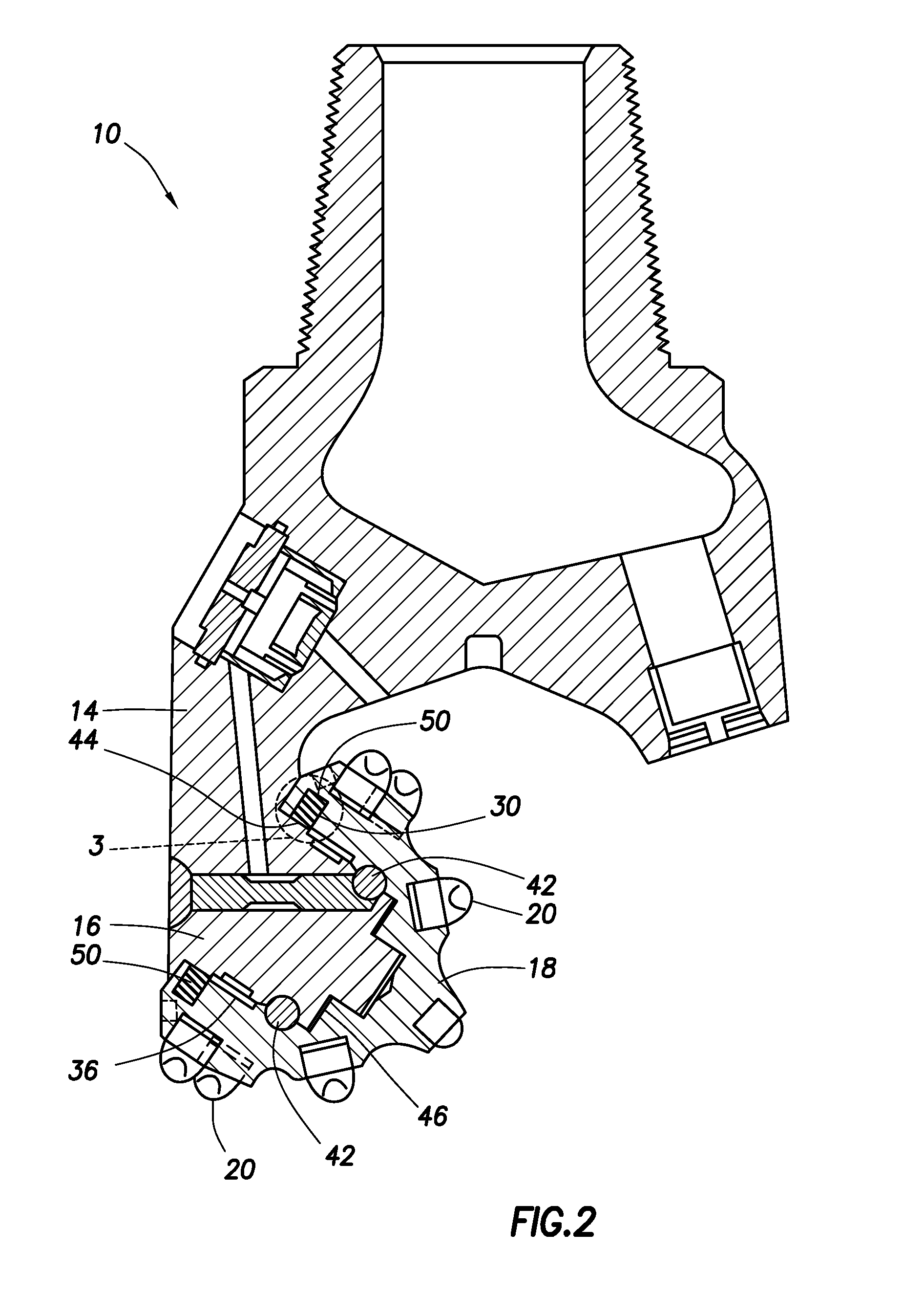
The patent describes a sealed and lubricated rolling cutter drill bit that has a seal in the seal groove of the cutter. The seal is designed to provide air gaps in the seal, which helps to prevent mud and grease from leaking out of the bit during use. The seal is installed in the seal groove and is compressed by downhole pressure, resulting in the formation of air gaps between the seal and the walls of the seal groove. The seal is made up of a ring-shaped seal body with an asymmetrical cross-section, a mud lobe, and a grease lobe. The seal helps to improve the performance and durability of the drill bit during use.

Problems solved by technology

In these designs, however, at a given operating RPM, as the diameter of the drill bit increases, the surface speed of the seal against its seal land may also increase such that, at the very large bit diameters common for motor bits, the sealing interface may be sliding against the seal land at quite high rates.
Otherwise, this can lead to rapid heating and early failure, especially if the seal is deformed with cutting packing into the seal groove.
Sealing large diameter bits may be challenging when providing radial cross-section elastomeric seals for drill bits of very large borehole diameters (e.g., about 12¼ inches (31.11 cm) or greater).
However, in some cases, the flushing system intended to carry the drilled earth to the surface may become overwhelmed to the point that the drill cuttings become packed around the drill bit and pack into a seal groove area of the drill bit.

Method used


Image

  • Drill bit seal and method of using same
  • Drill bit seal and method of using same
  • Drill bit seal and method of using same

Examples


Embodiment Construction

[0025]The description that follows includes exemplary systems, apparatuses, methods, and instruction sequences that embody techniques of the subject matter herein. However, it is understood that the described embodiments may be practiced without these specific details.

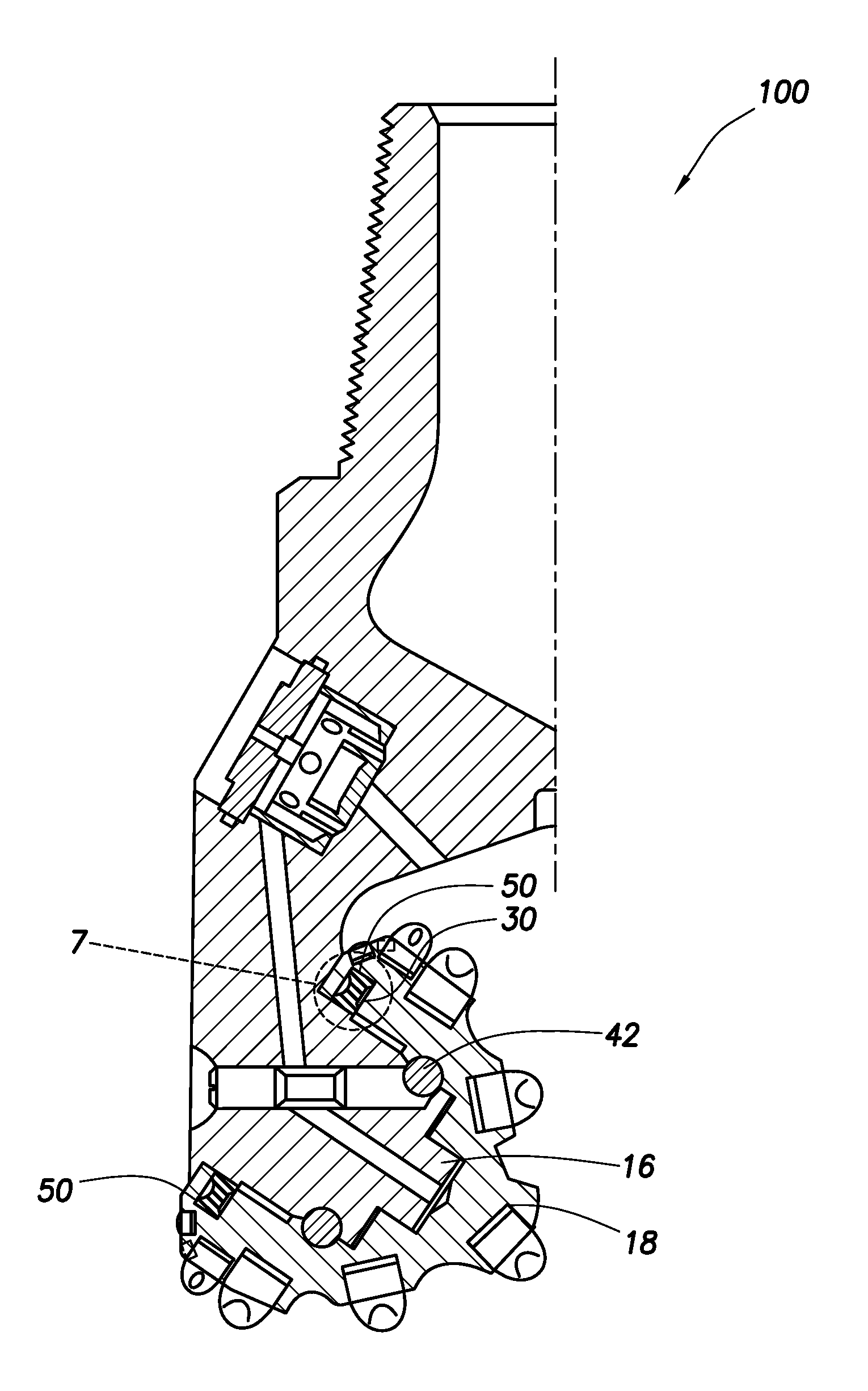
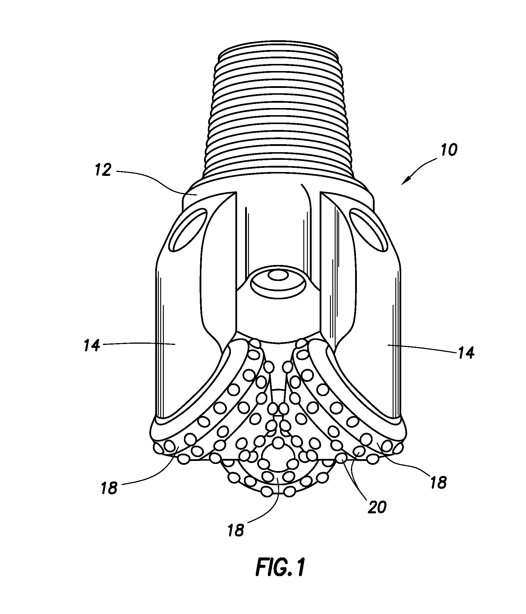
[0026]The present disclosure relates to a rolling cutter rock drill bit with a seal, such as a packing resistant type lip seal. The seal may be provided with an asymmetric configuration deformable within a seal groove of the drill bit under harsh conditions, such as downhole pressure (e.g., hydrostatic pressure, high hydrostatic pressure of greater than 1,000 kg / cm, and / or pressure from cuttings). The configuration may also be used to maintain a mud side lip of the seal in contact with a seal land of the seal groove. In some aspects, the seal may be provided with a spring to support the seal during operation, and / or a texturized pattern to trap lubricant and reduce running friction.

[0027]Referring now to FIG. 1, illust...


PUM


Abstract

A seal for a rolling cutter drill bit is provided. The seal has a ring shaped seal body having an inside diameter and an outside diameter, and a mud lobe and a grease lobe extending from the inside diameter of the seal body. The seal body has an asymmetrical, longitudinal cross-section such that, when positioned in a seal groove of the drill bit and compressed therein under downhole pressure, the mud lobe and grease lobe are maintained in contact with a seal land of the seal groove. The seal body may be provided with a garter spring and / or a textured pattern.

Description

BACKGROUND[0001]The present disclosure relates generally to drill bits for drilling a wellbore. The present disclosure is generally directed to seals, such as dynamic seals for roller cone drill bits, and, for example, a packing resistant radial lip seal that may be used on a relatively large diameter roller cone drill bit.[0002]Sealed and lubricated earth boring drill bits have been in use in the oil well drilling industry for several decades. In order to help reduce the friction at the radial seal interface, a means of enhancing lubrication by trapping it at the sealing interface may be provided, as described for example in U.S. Pat. No. 4,619,534. In these designs, however, at a given operating RPM, as the diameter of the drill bit increases, the surface speed of the seal against its seal land may also increase such that, at the very large bit diameters common for motor bits, the sealing interface may be sliding against the seal land at quite high rates. It may also be important ...

Claims


Application Information

Patent Timeline
IPC IPC(8): E21B10/25
CPCE21B10/25F16J15/164F16J15/162
Inventor BURR, BRUCE H.
Owner NAT OILWELL VARCO LP
Learn More