Construction machine

Inactive Publication Date: 2013-12-05
HITACHI CONSTR MASCH CO LTD
View PDF65 Cites 37 Cited by
  • Summary
  • Abstract
  • Description
  • Claims
  • Application Information

AI Technical Summary

Benefits of technology

[0022]With this arrangement, the bending deformation directions of the first exhaust pipe and the second exhaust pipe can be matched with all the three axial directions of the vehicle body, for example. Thus, the vibration of the engine and the first exhaust gas post-treatment device whose vibration modes are different from each other and/or the vibration of the first exhaust gas post-treatment device and the second exhaust gas post-treatment device whose vibration modes are different from each other can be stably absorbed by means of bending deformation of at least either of the first bellows pipe an

Problems solved by technology

However, the bellows pipe has its deformable amount (contraction amount) in its length direction (axial direction) small, and vibration absorbing capacity in the length direction is not high.
Therefore, in a case where the bellows pipe is made longer, the enti

Method used


Image

  • Construction machine
  • Construction machine
  • Construction machine

Examples


first embodiment

[0041]FIGS. 1 to 6 illustrate a hydraulic excavator according to the present invention.

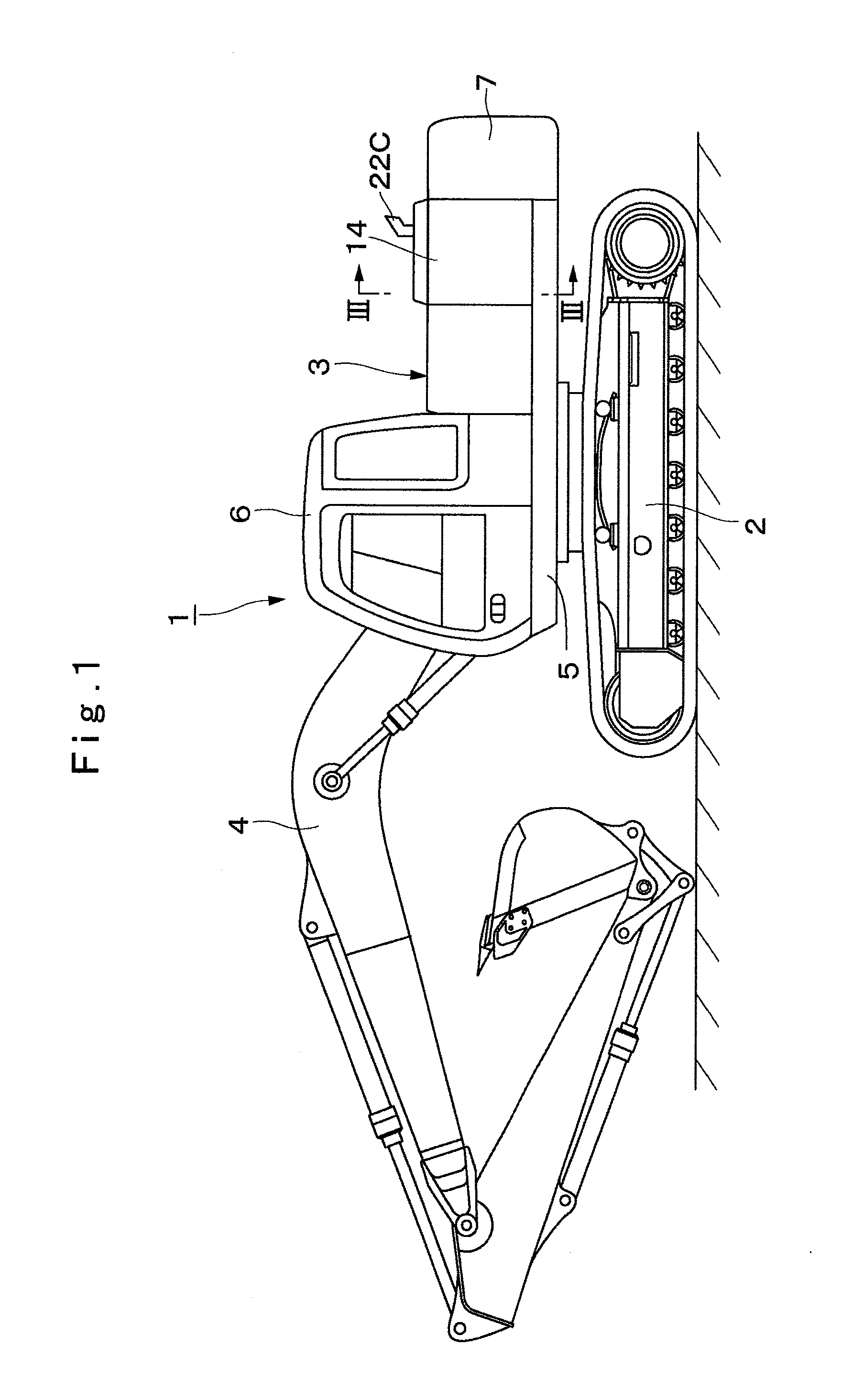
[0042]In the drawings, designated at 1 is a hydraulic excavator as a construction machine used for an excavating work of earth and sand or the like. This hydraulic excavator 1 is composed of an automotive crawler-type lower traveling structure 2, an upper revolving structure 3 rotatably mounted on the lower traveling structure 2 and constituting a vehicle body together with the lower traveling structure 2, and a working mechanism 4 liftably provided on the front side of the upper revolving structure 3.

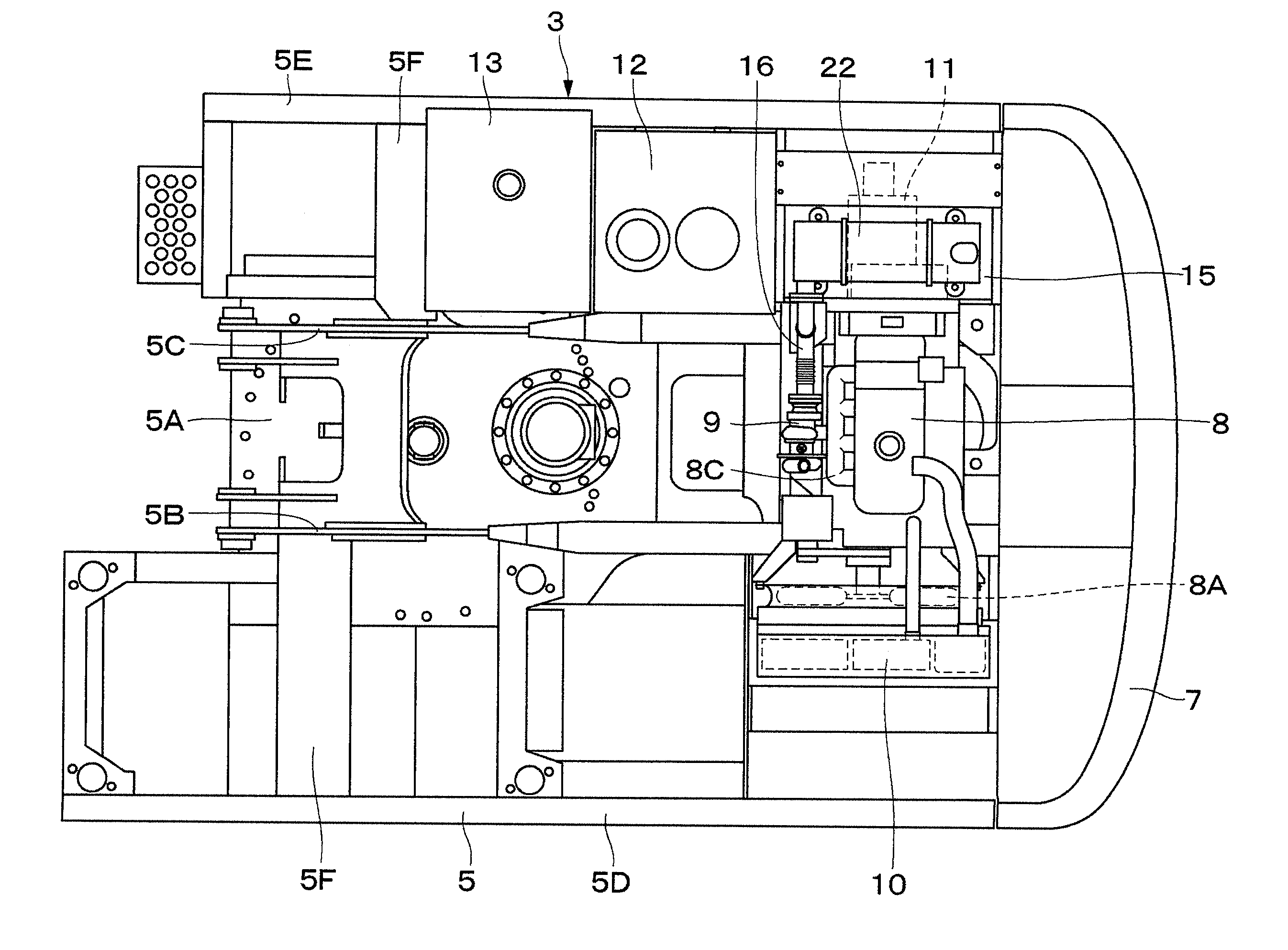
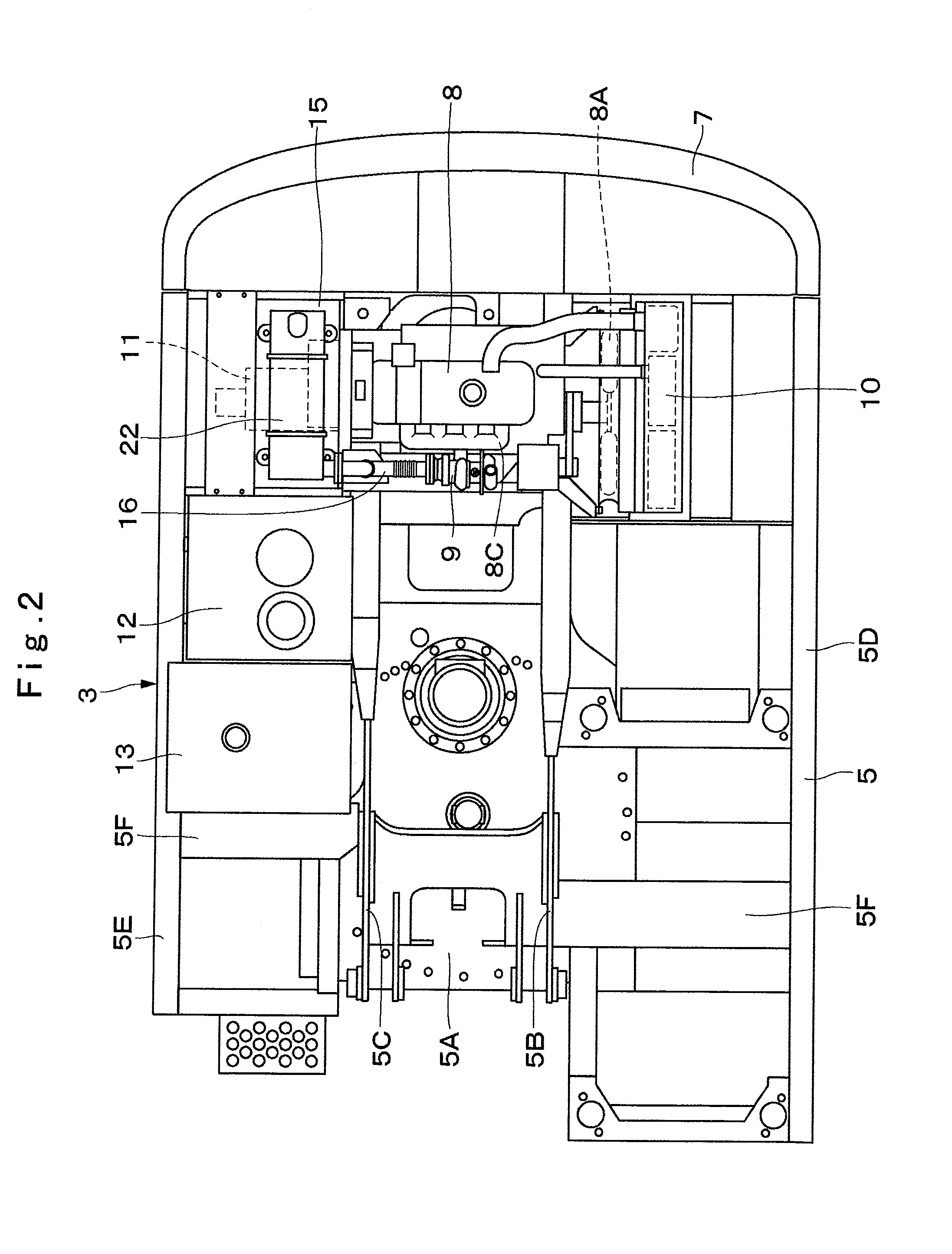
[0043]Here, the upper revolving structure 3 constituting the hydraulic excavator 1 will be described in detail. Indicated at 5 is a revolving frame of the upper revolving structure 3, and the revolving frame 5 is constituted as a support structural body. This revolving frame 5 is composed of a bottom plate 5A made of a thick steel plate or the like extending in the front-rear direction, a left vertic...

second embodiment

[0093]That is, during running or working of the hydraulic excavator 1, the exhaust gas post-treatment device 22 mounted on the engine 8 through the support member 31 and the vibration isolating member 22E vibrates in a vibration mode different from that of the engine 8. In this case, vibration between the engine 8 and the exhaust gas post-treatment device 22 can be absorbed by bending deformation of the first bellows pipe 18 and the second bellows pipe 20 arranged in the midway portion of the exhaust pipe 16.

[0094]Thus, similarly to the above described first embodiment, vibration between the engine 8 and the exhaust gas post-treatment device 22 can be stably absorbed by bending deformation of the first bellows pipe 18 and the second bellows pipe 20, and reliability of the hydraulic excavator 1 can be improved. Moreover, vibration can be stably absorbed even if the lengths of each of the bellows pipes 18 and 20 are made smaller, and freedom in arrangement of the exhaust pipe 16 can ...

third embodiment

[0110]That is, during running or working of the hydraulic excavator 1, the exhaust gas post-treatment device 22 mounted on the engine 8 through the support member 41 and the vibration isolating member 22E vibrates in a vibration mode different from that of the engine 8. In this case, the first bellows pipe 44 and the second bellows pipe 46 are provided through the connecting pipe 45 in the midway portion of the exhaust pipe 42 connecting the engine 8 and the exhaust gas post-treatment device 22 to each other. Each of these bellows pipes 44 and 46 is arranged with a positional relationship (more specifically, a positional relationship of crossing at a right angle) in which the axis line X2-X2 direction and the axis line Y2-Y2 direction cross each other.

[0111]As a result, vibration in the front-rear direction of the vehicle body generated between the engine 8 and the exhaust gas post-treatment device 22 can be absorbed by bending deformation of the first bellows pipe 44 in the front-...


PUM


Abstract

On an upper revolving structure, an engine having an exhaust port is mounted. In the midway portion of the exhaust pipe connecting the exhaust port of the engine and an exhaust gas post-treatment device, a first bellows pipe and a second bellows pipe are arranged through a connecting pipe having an L-shaped bending portion. In this case, the first bellows pipe and the second bellows pipe are arranged so as to have a positional relationship in which axis lines thereof (X1-X1, Z1-Z1) cross each other. That is, the first bellows pipe is arranged in a horizontal direction so that its axis line (X1-X1) extends in the left-right direction of the upper revolving structure. The second bellows pipe is arranged so that its axis line (Z1-Z1) matches the vertical direction of the upper revolving structure.

Description

TECHNICAL FIELD[0001]The present invention relates to a construction machine such as a hydraulic excavator provided with an exhaust gas post-treatment device on an exhaust pipe of an engine, for example.BACKGROUND ART[0002]In general, a hydraulic excavator which is a typical example of a construction machine is composed of an automotive lower traveling structure, an upper revolving structure rotatably mounted on the lower traveling structure, and a working mechanism liftably provided on the front side of the upper revolving structure. The upper revolving structure has a cab, a fuel tank, an operating oil tank and the like mounted on the front side of a revolving frame and has an engine for driving a hydraulic pump, a heat exchanger and the like mounted on the rear part of the revolving frame.[0003]In the hydraulic excavator in the conventional art, an exhaust pipe is connected to an exhaust port of the engine. On an outlet side of the exhaust pipe, the exhaust gas post-treatment dev...

Claims


Application Information

Patent Timeline
IPC IPC(8): E02F9/08
CPCE02F9/0866F01N13/1816F01N13/1822B60W2300/17F01N2590/08B60K13/04F01N2530/22E02F9/00F01N13/08
Inventor KOBAYASHI, TAKAHIRONAKAMURA, TSUYOSHISATO, KENSUKEAZUMA, HIROYUKI
Owner HITACHI CONSTR MASCH CO LTD
Why Eureka
Try Eureka