Bearing member, end member, photosensitive drum unit, process cartridge, and method for manufacturing bearing member

a technology of photosensitive drum unit and bearing member, which is applied in the direction of bearing unit rigid support, coupling, instruments, etc., can solve the problems of superior accuracy, assembly precision deterioration or fracture of parts during assembly, and other problems in attaching

Active Publication Date: 2013-12-05
MITSUBISHI CHEM CORP
View PDF2 Cites 27 Cited by
  • Summary
  • Abstract
  • Description
  • Claims
  • Application Information

AI Technical Summary

Benefits of technology

[0049]The shaft member may be inserted into the bearing member from an end opposite to an end to which a photosensitive drum is fitted, and

Problems solved by technology

Assembly involving forceful insertion and forceful pullout might deteriorate assembly precision or fracture parts during assembly.
Further, another difficulty is encountered in attaching, with superior accuracy, the drum flange (the bearing member) outfitted with such a swayable coupling member to an end of th

Method used


Image

  • Bearing member, end member, photosensitive drum unit, process cartridge, and method for manufacturing bearing member
  • Bearing member, end member, photosensitive drum unit, process cartridge, and method for manufacturing bearing member
  • Bearing member, end member, photosensitive drum unit, process cartridge, and method for manufacturing bearing member

Examples


first embodiment

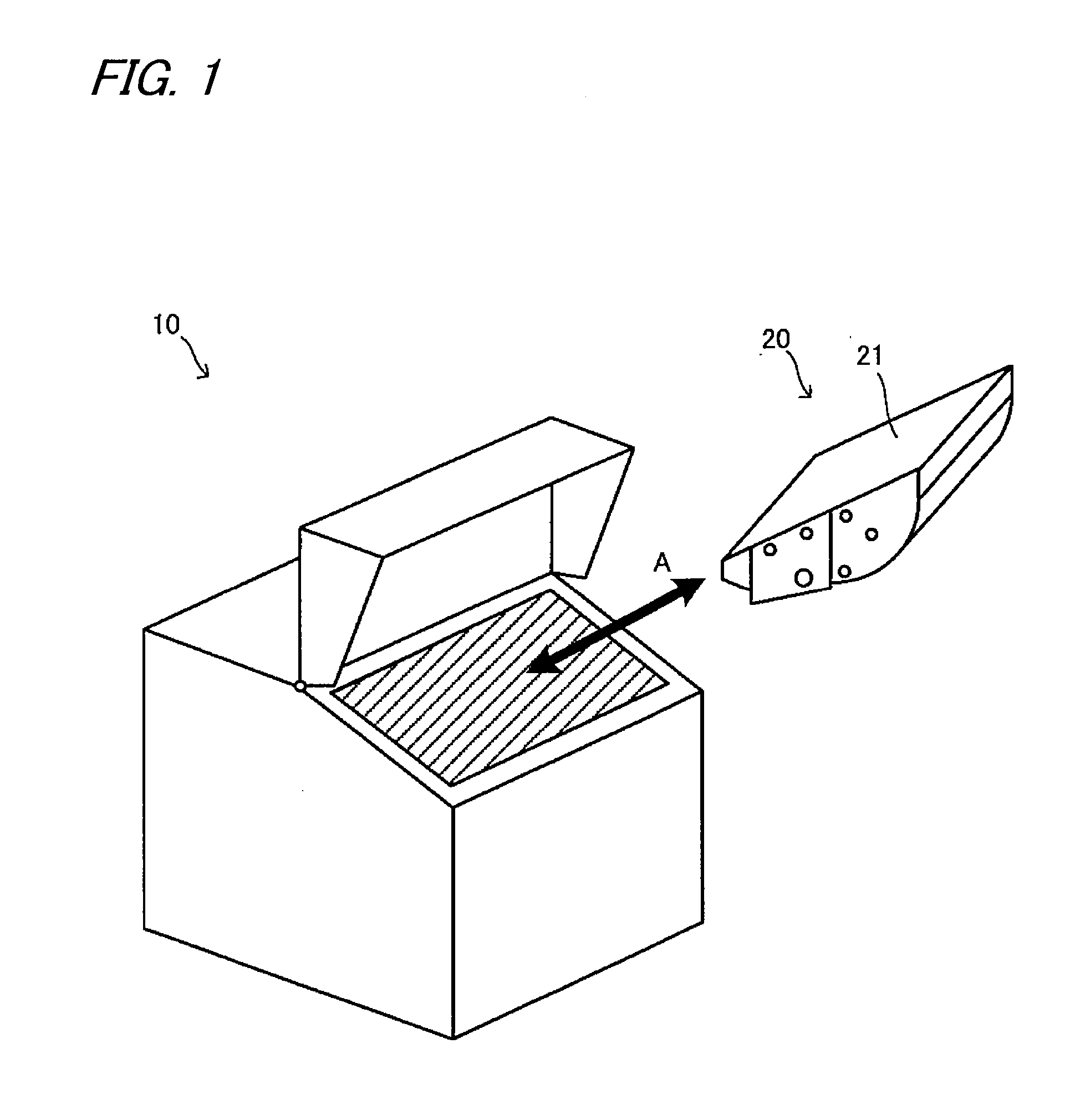
[0093]FIG. 1 is a drawing for describing a first embodiment; namely, a perspective view schematically showing a process cartridge 20 with an end member 40 (see FIG. 2) and an image forming apparatus main body 10 (hereinafter often referred to as a “main body 10”) that is used when outfitted with the process cartridge 20. As shown in FIG. 1, the process cartridge 20 can be attached to or detached from the main body 10 by being shifted in a direction designated by reference symbol A in FIG. 1. The direction is different from an axial direction of a drive shaft of the main body 10. The image forming apparatus is built from the main body 10 and the process cartridge 20. Detailed explanations are provided hereunder.

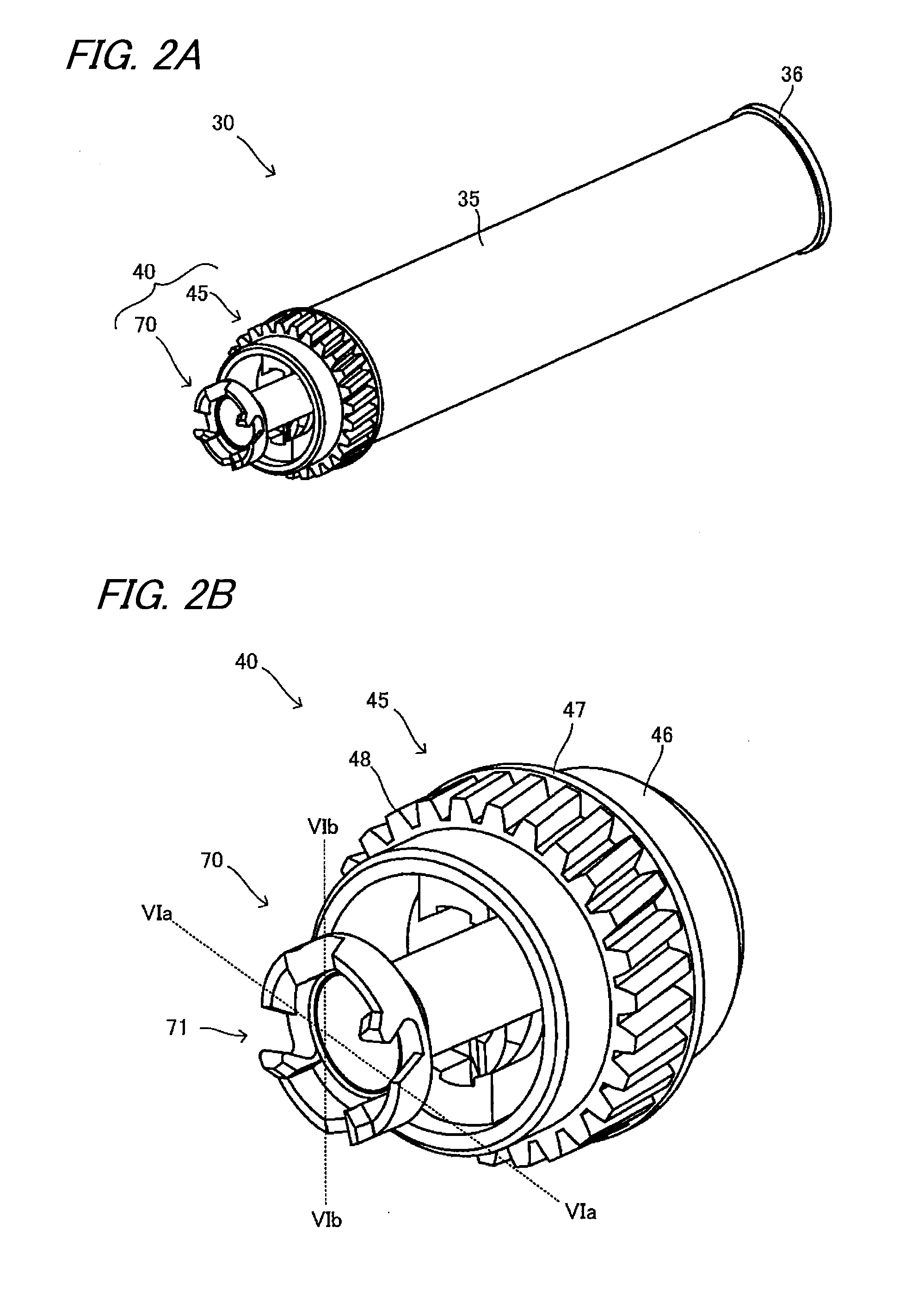
[0094]The process cartridge 20 has a housing 21 that defines a contour of the process cartridge 20, and a variety of parts are included in the housing 21. In the embodiment, the process cartridge 20 is specifically equipped with a photosensitive drum unit 30 (see FIG. 2A), an ...

second embodiment

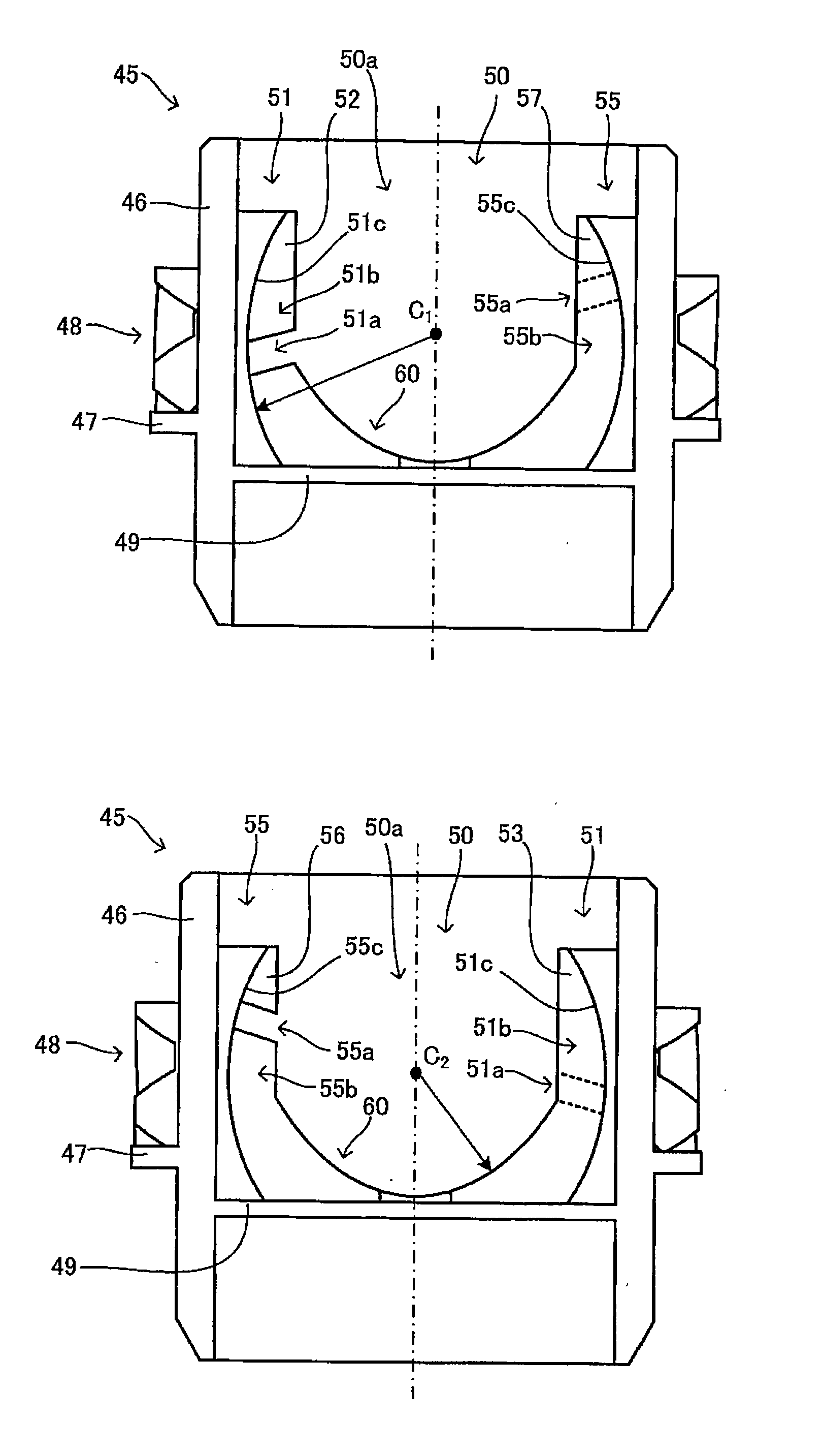
[0176]FIGS. 16A and 16B are drawings for explaining the second embodiment, showing a bearing member 45′. FIG. 16A is a perspective view, and FIG. 16B is a plan view of the bearing member 45′ acquired when FIG. 16A is viewed in its axial direction. As hatched along with reference symbol XVI in FIGS. 16A and 16B, a portion of a pedestal 60′ of a retaining portion 50′ passes through the bottom 49′ to the other side in the bearing member 45′.

[0177]The through area XVI serves as a cavity for use in injection molding, whereby the bearing member 45′ can be efficiently produced by injection molding.

third embodiment

[0178]FIG. 17 is a drawing for explaining a third embodiment that is a perspective view of a bearing member 145 of the embodiment. FIG. 18 is a drawing of FIG. 17 that is viewed from an axial direction in which the shaft member 70 is inserted. FIG. 19A is a drawing in which a cross section XIX-XIX shown in FIG. 18 is viewed in a direction of arrow XIXa, and FIG. 19B is a drawing in which the cross section XIX-XIX shown in FIG. 18 is viewed in a direction of arrow XIXb. FIG. 20A is a drawing in which a cross section XX-XX shown in FIG. 18 is viewed in a direction of arrow XXa, and FIG. 20B is a drawing in which the cross section XX-XX shown in FIG. 18A is viewed in a direction of arrow XXb. In FIGS. 19A, 19B, 20A, and 20B, an end face (a cutting plane) in the cross section is denoted as being hatched.

[0179]Like the bearing member 45, the bearing member 145 has the cylindrical body 46, the contact wall 47, and the gear 48. As is well illustrated in FIG. 17, a plurality of recesses 46a...


PUM

PropertyMeasurementUnit
Diameteraaaaaaaaaa
Lengthaaaaaaaaaa
Sizeaaaaaaaaaa

Abstract

A bearing member placed at an end of a photosensitive drum, and a shaft member is attached thereto. The bearing member has a cylindrical body and a retaining portion placed in the cylindrical body, retaining a torque transmission pin provided in the shaft member, and removably provided. The retaining portion is provided with swaying grooves at least two grooves extending in an axial direction of the cylindrical body, placed opposite each other, and whose bottoms have each a curved surface exhibiting a bow with respect to the axial direction; inlet grooves at one end thereof connected to the respective swaying grooves and at the other end thereof connected to outside of the retaining portion and placed at an upstream position with respect to the swaying grooves along a direction of rotation of the cylindrical body; and a pedestal interposed, at one end, between the two swaying grooves.

Description

BACKGROUND OF THE INVENTION[0001]The invention relates to a process cartridge removably fitted in an image forming apparatus, like a laser printer and a copier, a photosensitive drum unit fitted in the process cartridge, an end member attached to a photosensitive drum of the photosensitive drum unit, a bearing member that makes up of the end member, and a method for manufacturing the bearing member.[0002]In relation to an image forming apparatus, like a laser printer and a copier, a main body of the image forming apparatus (hereinafter often mentioned as a “main body”) is removably outfitted with a process cartridge.[0003]The process cartridge is a member that forms details to be represented, such as letters and graphics, and transfers the details onto a recording medium, like paper. More specifically, the process cartridge is outfitted with a photosensitive drum, and details to be transferred are formed on the photosensitive drum. The process cartridge is additionally provided with...

Claims


Application Information

Patent Timeline
IPC IPC(8): F16C17/02B29D99/00F16C33/02
CPCB29D99/00F16C17/02F16C33/02F16D1/10F16D3/44G03G15/757F16D3/2052B29C45/2616B29C45/44
Inventor IKEDA, SHUICHI
Owner MITSUBISHI CHEM CORP
Why Eureka
Try Eureka