
Method of making color golf ball and resulting color golf ball

Active Publication Date: 2013-12-05
ACUSHNET CO
View PDF9 Cites 4 Cited by
  • Summary
  • Abstract
  • Description
  • Claims
  • Application Information

AI Technical Summary

Benefits of technology

The present invention relates to a method for reducing the hardness of golf ball cores and to golf balls with reduced surface hardness. The method involves treating the core with a surface-softening material comprising at least one fatty acid or fatty acid salt composition. The treatment results in a treated core with a lower hardness measurement compared to the untreated core. The fatty acid or fatty acid salt composition acts as a plasticizer to penetrate and soften the core surface. The resulting core has a hardness gradient between the treated outer surface and other core regions within the core. The fatty acid or fatty acid salt composition permanently embeds itself between polymer chains, spacing them apart and increasing free volume. The treated core is then covered with at least one cover layer to form the golf ball. The invention is useful for improving the feel and performance of golf balls.

Problems solved by technology

However, golf ball manufacturing costs increase when colorants distribute poorly and / or unevenly throughout golf ball compositions during processing (e.g., injection molding, extrusion, etc.).
Such poor distribution occurs, for example, when a colorant is not thermally stable at the required golf ball composition processing temperature.
And poor colorant distribution / dispersion within the golf ball composition results in undesirable color variations such as streaking and / or localized areas of color fading, which not only raise production costs but also impair the golf ball's aesthetics.
However, master batches are expensive and also become “overkill” in instances where, for example, the chosen / desired golf ball component surface color could easily be achieved without coloring the entire depth or thickness of the component / coating.
In this approach, however, poor golf ball durability results when poor adhesive strength presents between the paint and the substrate—especially, for example, in a painted cover when struck by a golf club face.
Such poor durability increases manufacturing costs and also negatively impacts reputation.

Method used


Image

  • Method of making color golf ball and resulting color golf ball
  • Method of making color golf ball and resulting color golf ball
  • Method of making color golf ball and resulting color golf ball

Examples


Embodiment Construction

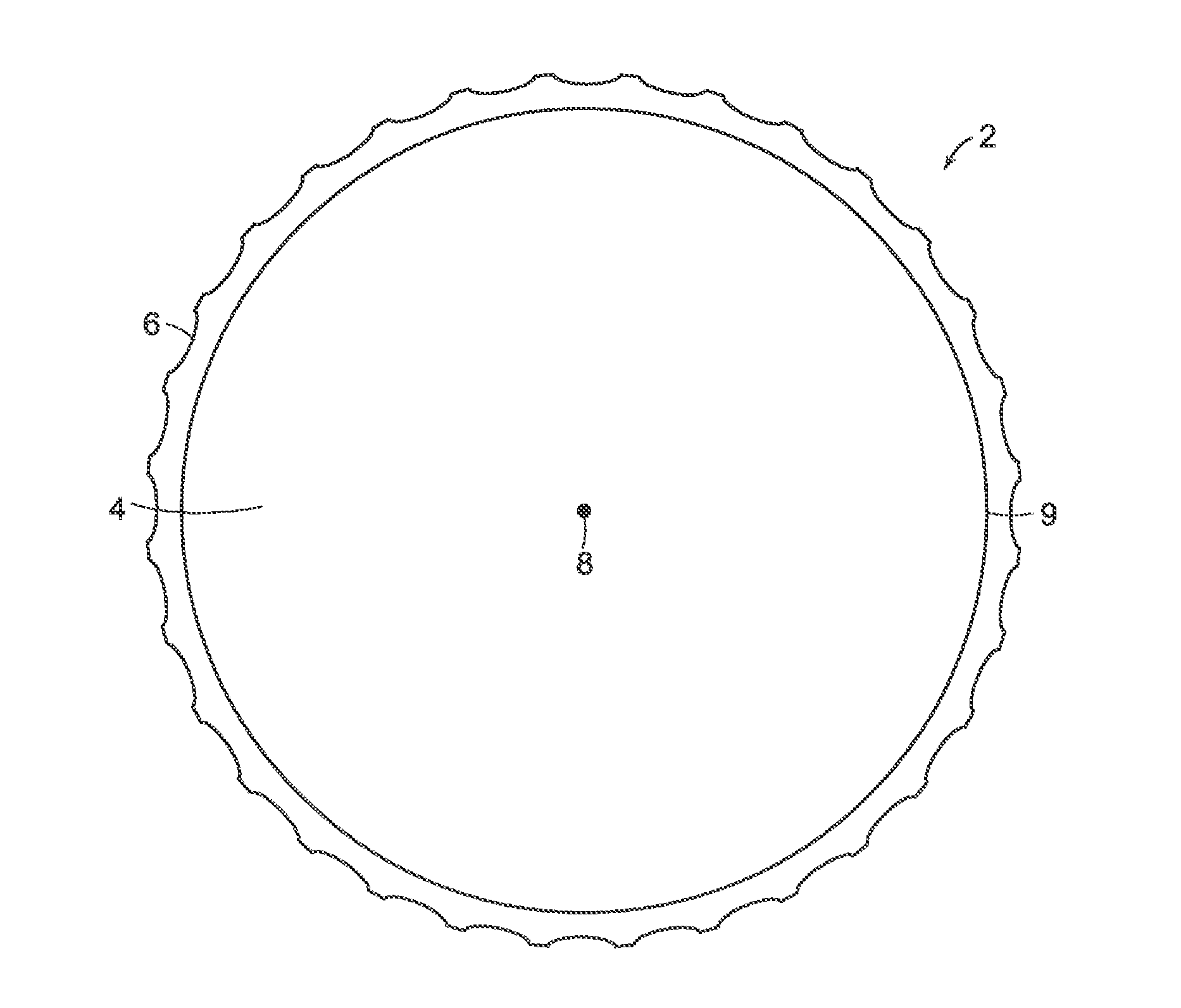
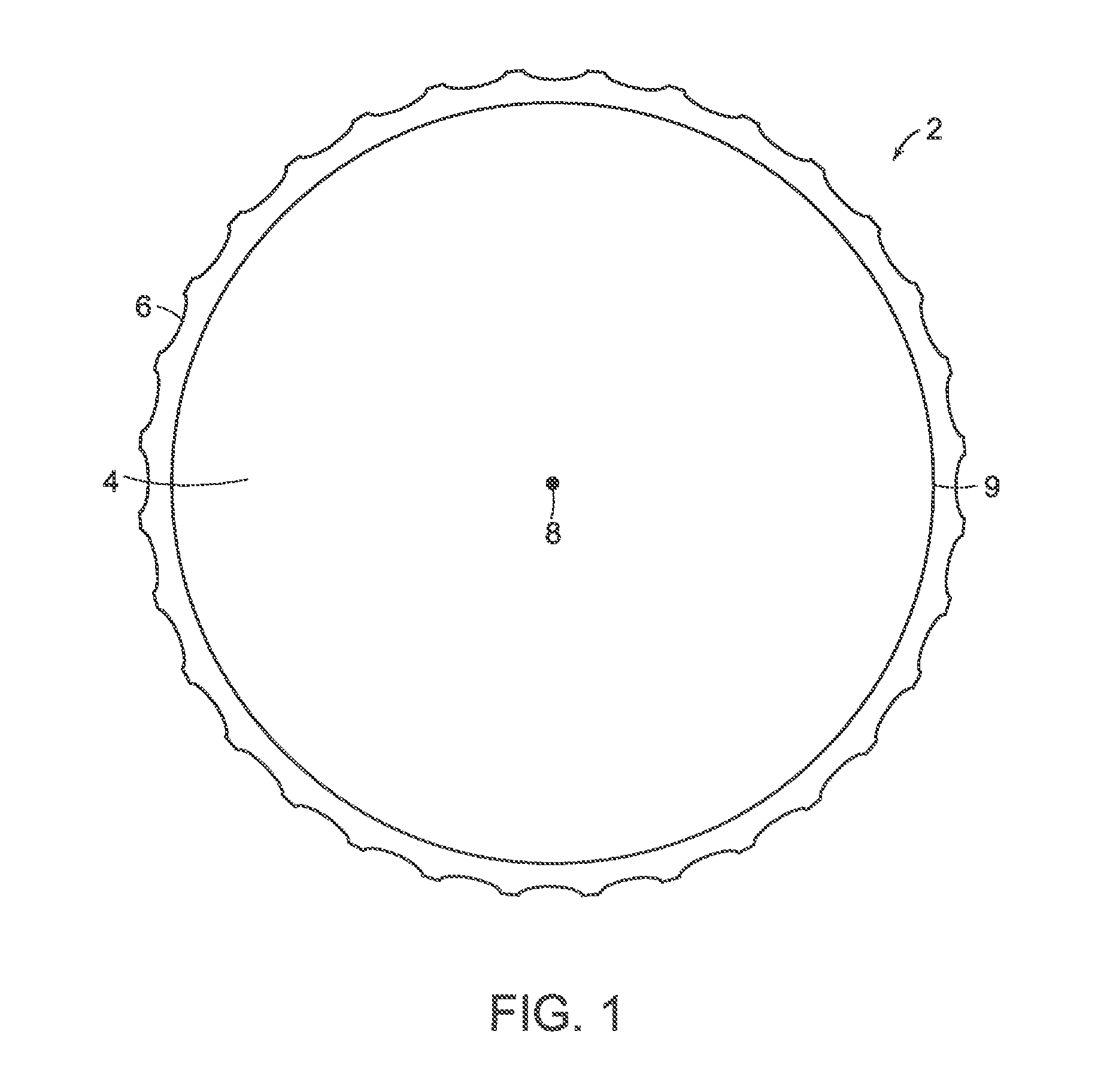
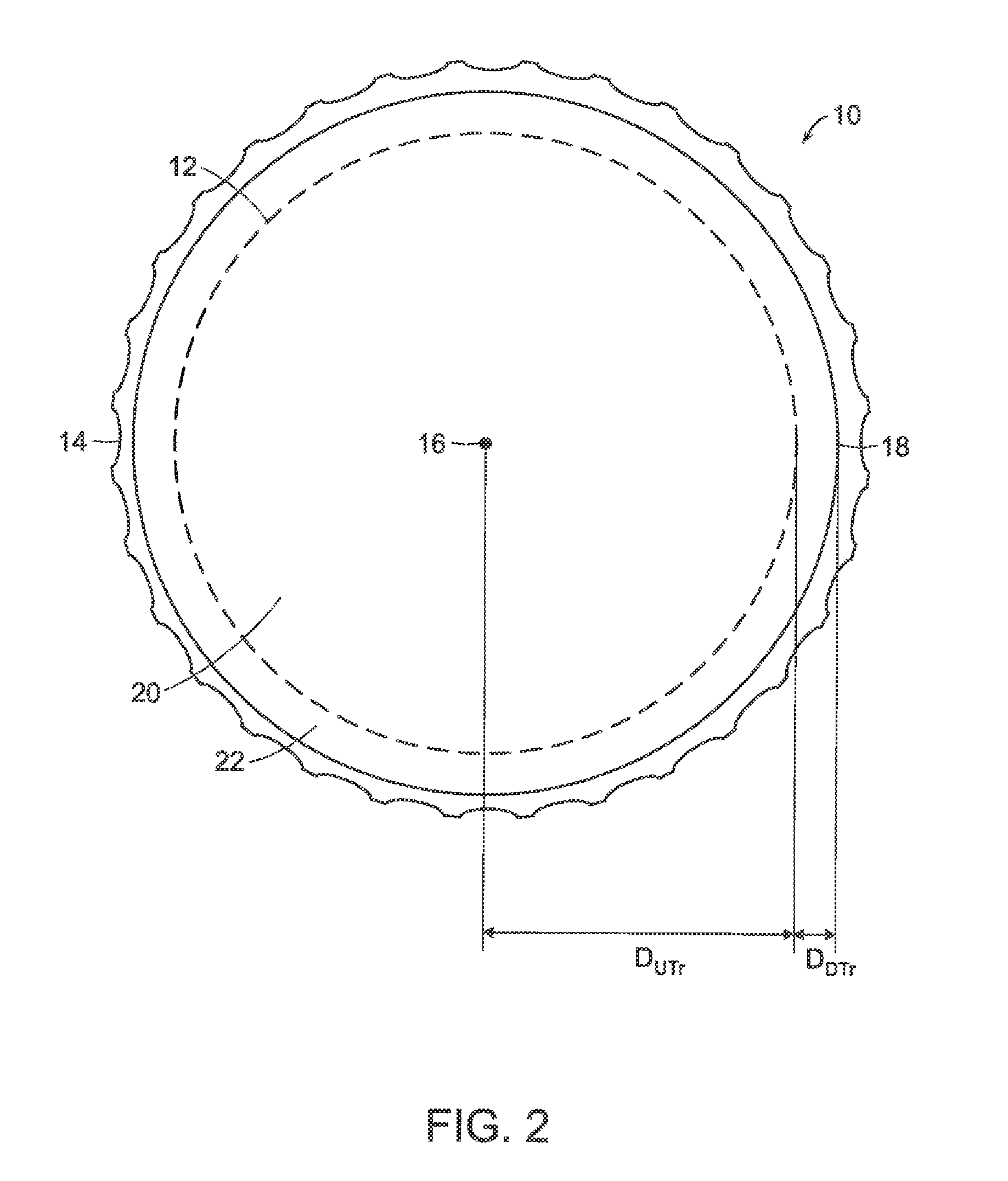
[0068]In the method and golf ball of the invention, the surface-penetrating color composition may comprise a fatty acid and / or fatty acid salt colorant composition.

A color gradient is achieved between a treated portion and an untreated portion of a given golf ball component (i.e., core or center, core layer(s), intermediate layer(s), cover layer(s), and / or coating). The treated portion, e.g., an outer surface or region of the golf ball component is treated with and comprises the fatty acid and / or fatty acid salt colorant composition. Meanwhile, the untreated portion or region within the component is not treated with and does not comprise the fatty acid and / or fatty acid salt colorant composition. The fatty acid and / or fatty acid salt colorant composition embeds within the treated surface and becomes part of the component, thereby creating the color gradient between the treated and untreated regions within the golf ball component. For example, a color gradient may be formed between a...


PUM

PropertyMeasurementUnit
Coloraaaaaaaaaa
Ratioaaaaaaaaaa
Depthaaaaaaaaaa

Abstract

A method and golf ball incorporating a surface penetrating color composition comprising a colorant (e.g. dyes, tints, color effects, etc.) in a portion (surface or region) of a golf ball component or coating (substrate). The substrate is formed from a homogenous composition having a color C1 which may comprise any color within the spectrum of visible light, or be clear colorless, and alternatively, may also be opaque, translucent, or clear colored, for example. An outer surface of the substrate is treated with or otherwise exposed to a surface penetrating color composition having a C2 that is different than C1 in some respect such as hue, chroma, saturation and / or opacity. The surface penetrating color composition penetrates the golf ball substrate surface to a target depth and becomes embedded within the surface, thereby forming a surface penetrating color composition-treated component or coating having a treated region and an untreated region.

Description

CROSS REFERENCE TO RELATED APPLICATIONS[0001]This application is a continuation of co-pending U.S. patent application Ser. No. 13 / 958,889, filed Aug. 5, 2013, which is a continuation-in-part of: co-pending U.S. patent application Ser. No. 12 / 781,281 (“'281 application”), filed on May 17, 2010; co-pending U.S. patent application Ser. No. 12 / 786,245 (“'245 application”), filed on May 17, 2010; co-pending U.S. patent application Ser. No. 13 / 153,535 (“'535 application”), filed on Jun. 6, 2011; and co-pending U.S. patent application Ser. No. 13 / 153,525 (“'525 application”), filed on Jun. 6, 2011. The '281 application is a continuation of the '245 application, which is a continuation-in-part of U.S. patent application Ser. No. 12 / 695,579 (“'579 application), filed Jan. 28, 2010, now U.S. Pat. No. 8,047,932, which is a continuation of U.S. patent application Ser. No. 12 / 695,379, filed Jan. 28, 2010, now U.S. Pat. No. 8,454,454, which is a continuation-in-part of U.S. patent application Ser...

Claims


Application Information

Patent Timeline
IPC IPC(8): A63B45/00
CPCA63B45/00A63B37/0022A63B37/0039A63B37/0051A63B37/0059A63B45/02C08K5/098B05D5/06C08L21/00
Inventor ZIESKE, NATHANKUNTIMADDI, MANJARIHOGGE, MATTHEW F.SULLIVAN, MICHAEL J.BINETTE, MARK L.COMEAU, BRIAN
Owner ACUSHNET CO
Learn More