Motor drive method, motor drive device, and brushless motor
a motor drive and motor technology, applied in the direction of motor/generator/converter stopper, electronic commutator, dynamo-electric converter control, etc., can solve the problem of surge energy not being absorbed more, load dump generation, etc., to prevent the power supply voltage supply from increasing, increase the current flowing through the coil, and prevent the effect of voltage increas
- Summary
- Abstract
- Description
- Claims
- Application Information
AI Technical Summary
Benefits of technology
Problems solved by technology
Method used
Image
Examples
first exemplary embodiment
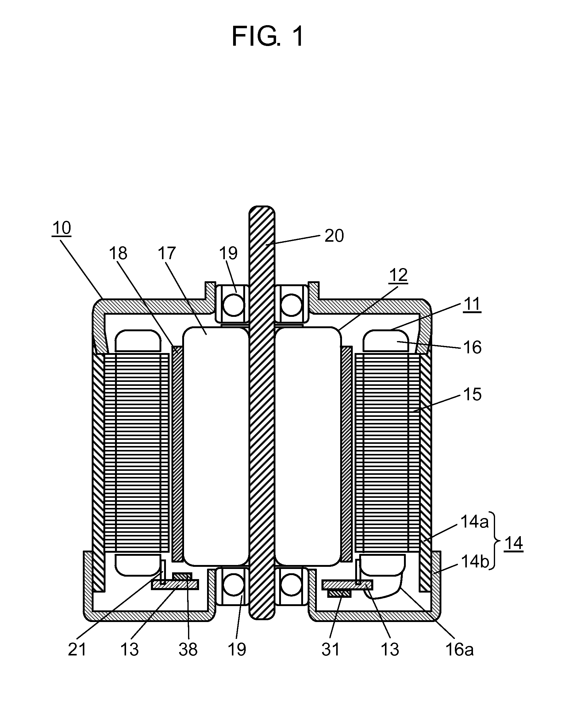
[0028]FIG. 1 is a view showing a structure of brushless motor 10 according to a first exemplary embodiment of the present invention. According to this exemplary embodiment, a description will be given of a case of an inner rotor type brushless motor in which a rotor is rotatably arranged on an inner periphery side of a stator. The brushless motor according to this exemplary embodiment has coils having a plurality of phases, and is rotationally driven by a signal which is pulse width modulated (hereinafter, referred to as PWM occasionally) for each phase.
[0029]As shown in FIG. 1, brushless motor 10 includes stator 11, rotor 12, circuit substrate 13, and motor case 14. Motor case 14 is made of metal formed into a sealed cylindrical shape, and brushless motor 10 is configured in such a manner that stator 11, rotor 12, and circuit substrate 13 are housed in motor case 14. Motor case 14 is composed of case body 14a and case lid 14b, and case lid 14b is mounted on case body 14a, whereby m...
second exemplary embodiment
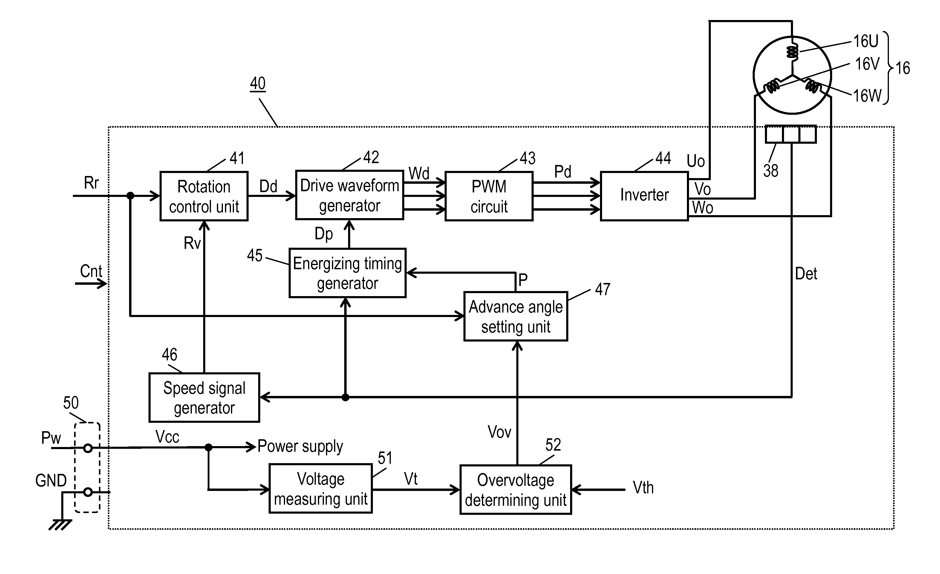
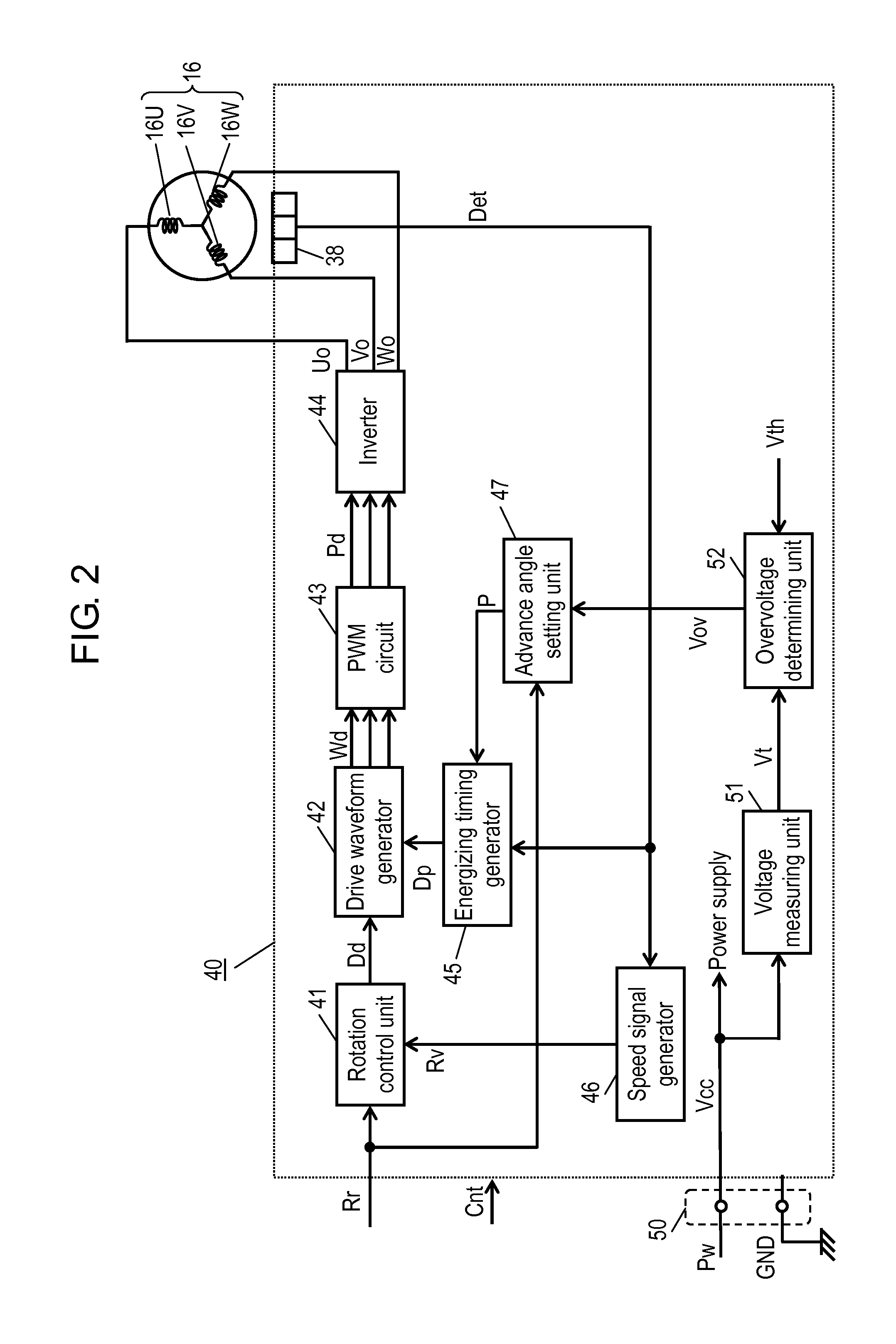
[0068]FIG. 6 is a block diagram of motor drive device 60 according to a second exemplary embodiment. In this exemplary embodiment, similar to the first exemplary embodiment, motor drive device 60 is incorporated or integrated in brushless motor 10 shown in FIG. 1. Referring to FIG. 6, the same components as those in FIG. 2 are marked with the same reference marks, and their detailed description is omitted. Motor drive device 60 further includes timer 56 and cutoff control unit 57, compared with motor drive device 40 shown in FIG. 2.
[0069]Timer 56 receives overvoltage determined signal Vov from overvoltage determining unit 52. When it is determined to be the overvoltage in overvoltage determined signal Vov, timer 56 starts measuring a time from the determined time. While it is determined to be the overvoltage, timer 56 continues to measure the time from the time when it is determined to be the overvoltage for the first time until the present time so as to measure a period while it is...
third exemplary embodiment
[0083]FIG. 9 is a block diagram of motor drive device 80 in a third exemplary embodiment. Similar to the first and second exemplary embodiments, in this exemplary embodiment also, motor drive device 80 is incorporated or integrated in brushless motor 10 shown in FIG. 1. In FIG. 9, the same components as those in FIGS. 2 and 6 are marked with the same reference marks and their detailed description is omitted. Compared with the first exemplary embodiment, motor drive device 80 includes overvoltage determining unit 82 for determining the overvoltage in two stages, and further includes cutoff control unit 57 similar to the second exemplary embodiment.
[0084]Similar to the first exemplary embodiment, overvoltage determining unit 82 receives power supply voltage value Vt from voltage measuring unit 51. Overvoltage determining unit 82 determines whether or not power supply voltage Vcc is the overvoltage exceeding a first predetermined voltage and whether or not it is the overvoltage exceedi...
PUM
 Abstract
Description
Claims
Application Information
 - R&D
- Intellectual Property
- Life Sciences
- Materials
- Tech Scout
- Unparalleled Data Quality
- Higher Quality Content
- 60% Fewer Hallucinations
Browse by: Latest US Patents, China's latest patents, Technical Efficacy Thesaurus, Application Domain, Technology Topic, Popular Technical Reports.
© 2025 PatSnap. All rights reserved.Legal|Privacy policy|Modern Slavery Act Transparency Statement|Sitemap|About US| Contact US: help@patsnap.com


