
Image processing apparatus, image processing method, image pickup apparatus, method of controlling image pickup apparatus, and non-transitory computer-readable storage medium

a technology of image processing and image pickup, which is applied in the field of image processing apparatus, image processing method, image pickup apparatus, and non-transitory computer-readable storage medium, can solve the problems of deteriorating spatial resolution and not considering the effect of subpixel shift and super-resolution, so as to improve the resolution of the main object

Active Publication Date: 2013-12-12
CANON KK
View PDF9 Cites 46 Cited by
  • Summary
  • Abstract
  • Description
  • Claims
  • Application Information

AI Technical Summary

Benefits of technology

The present invention relates to an image pickup apparatus and a method for controlling it. The technical effects of this invention include generating multiple second images with different focus positions and improving the resolution of the main object in accordance with the shift amount of pixels that are combined by the reconstruction. The method includes performing a first focus adjustment to adjust the position of an reference object and a second focus adjustment to move the position of the main object. The non-transitory computer-readable storage medium stores a program that performs the same steps as the method described.

Problems solved by technology

Therefore, a spatial resolution is deteriorated compared to an image pickup apparatus which stores only the two-dimensional light intensity distribution of the light.
However, it does not consider how to change the effect of the super-resolution from subpixel shift when an image is generated at a plurality of focus position different from each other.

Method used


Image

  • Image processing apparatus, image processing method, image pickup apparatus, method of controlling image pickup apparatus, and non-transitory computer-readable storage medium
  • Image processing apparatus, image processing method, image pickup apparatus, method of controlling image pickup apparatus, and non-transitory computer-readable storage medium
  • Image processing apparatus, image processing method, image pickup apparatus, method of controlling image pickup apparatus, and non-transitory computer-readable storage medium

Examples


embodiment 1

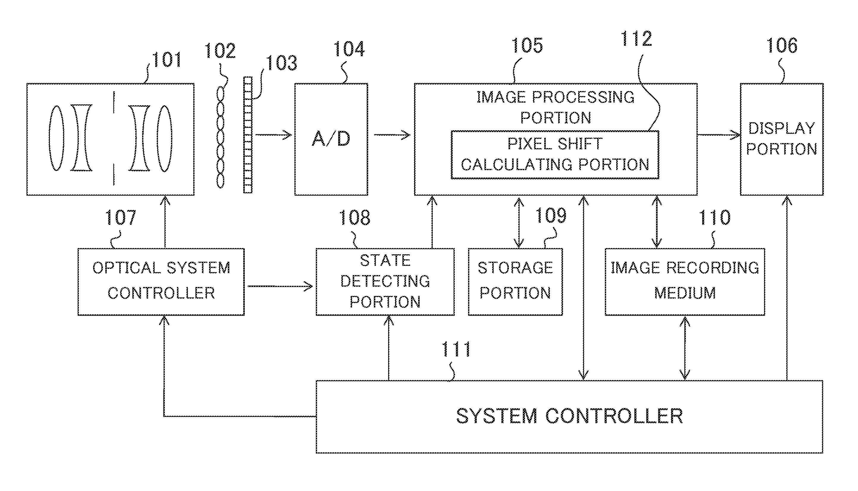
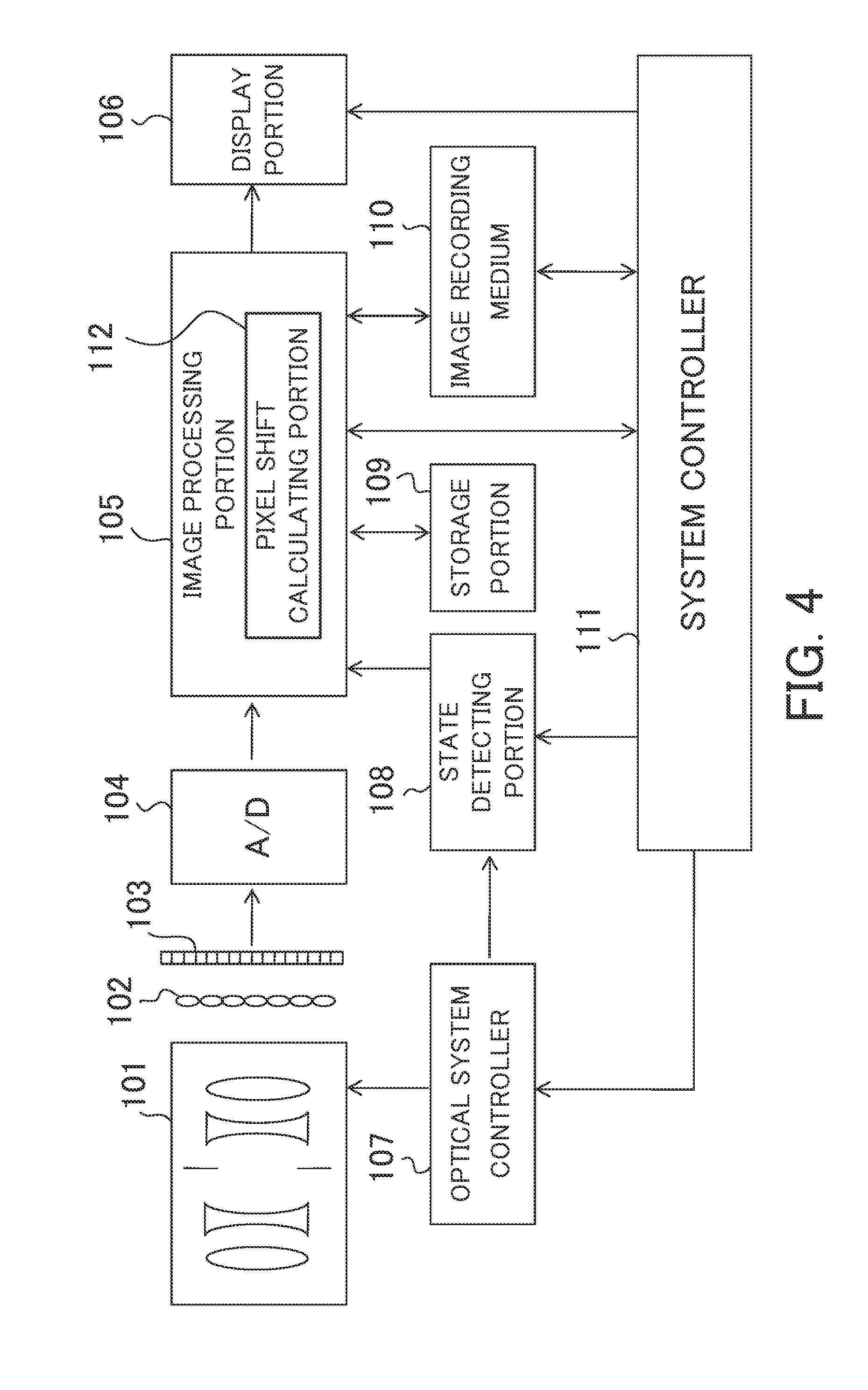
[0037]First of all, referring to FIG. 4, a configuration of an image pickup apparatus in Embodiment 1 of the present invention will be described. FIG. 4 is a block diagram of the image pickup apparatus in the present embodiment. An image processing method of the present embodiment is performed by an image processing portion 105 of the image pickup apparatus.

[0038]A pupil dividing portion 102 enables a ray from the same position on an object plane to enter pixels of an image pickup element 103 which are different from each other in accordance with a pupil region of an imaging optical system 101 where the ray passes. The image pickup element 103 is a two-dimensional image pickup element such as a CCD (Charge Coupled Device) or a CMOS (Complementary Metal-Oxide Semiconductor), which includes a plurality of pixels. An energy of the ray that enters the image pickup element 103 via the imaging optical system 101 (a main lens unit) and the pupil dividing portion 102 is converted to an elec...

embodiment 2

[0068]Next, Embodiment 2 of the present invention will be described. A basic configuration of an image pickup apparatus in the present embodiment is the same as that of the image pickup apparatus of Embodiment 1 described with reference to FIG. 4, and therefore descriptions thereof will be omitted.

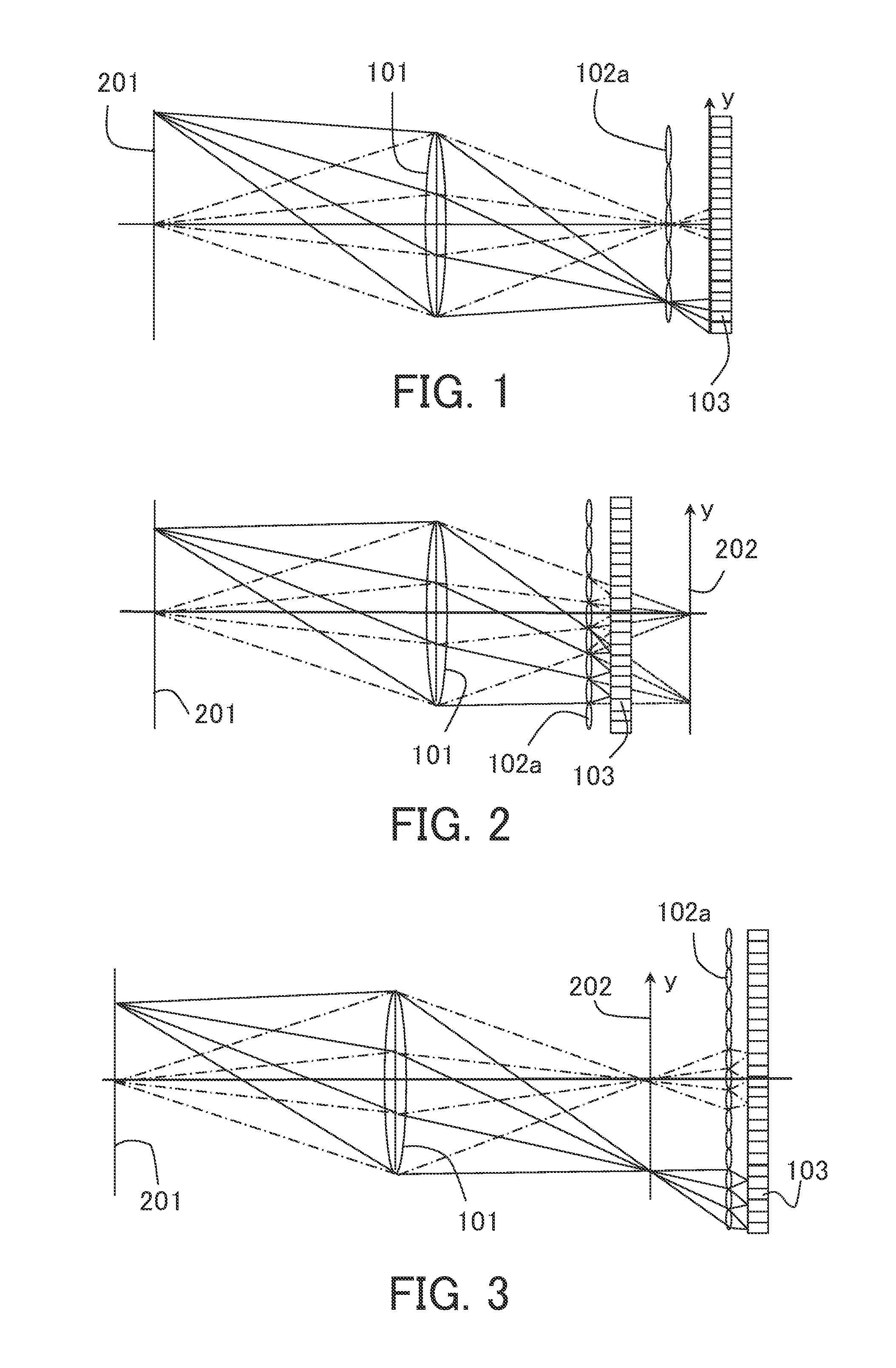
[0069]Subsequently, referring to FIG. 2, a configuration of an image pickup optical system in the present embodiment will be described. FIG. 2 is a schematic configuration diagram of the image pickup optical system. The lens array 102a is disposed at the object side relative to an image side conjugate plane 202 of the imaging optical system 101 with respect to the object plane 201, and the image side conjugate plane 202 and the image pickup element 103 are disposed so as to conjugate to each other via the lens array 102a. A ray from the object plane 201 passes through the imaging optical system 101 and the lens array 102a, and then enters pixels of the image pickup element 103 different fr...

embodiment 3

[0093]Next, Embodiment 3 of the present invention will be described. The present embodiment describes an image processing apparatus (an image processing system) that performs the image processing method described above. FIG. 11 is a block diagram of the image processing system in the present embodiment.

[0094]As illustrated in FIG. 11, the image processing system includes an image pickup apparatus 301. For example, the image pickup apparatus 301 includes the image pickup optical system illustrated in FIG. 3. An image processing apparatus 302 is a computer device (an information processing apparatus) that performs the pixel shift calculating step and the image generating step described above. The image processing apparatus 302 performs the image generating step in which the reconstruction depending on the configuration of the image pickup apparatus 301 for an image obtained by the image pickup apparatus 301 is performed so as to generate the output image. The result of the image gener...


PUM


Abstract

An image processing method is capable of performing a reconstruction for an input image so as to generate a plurality of output images having a plurality of focus positions different from each other, and the image processing method includes the steps of obtaining the input image that is an image containing information of an object space obtained from a plurality of points of view using an image pickup apparatus having an imaging optical system and an image pickup element including a plurality of pixels, and calculating a pixel shift amount of pixels that are to be combined by the reconstruction for a plurality of virtual imaging planes corresponding to the plurality of focus positions.

Description

BACKGROUND OF THE INVENTION[0001]1. Field of the Invention[0002]The present invention relates to an image processing method that is capable of performing a reconstruction for an input image so as to generate a plurality of output images that have focus positions different from each other.[0003]2. Description of the Related Art[0004]Recently, an image pickup apparatus that performs a calculation using data obtained by an image pickup element and performs a corresponding digital image processing so as to output various images is proposed. Ren Ng, et al., “Light Field Photography with a Hand-held Plenoptic Camera”, 2005 Computer Science Technical Report CTSR, and Todor Georgiev, et al., “Superresolution with Plenoptic 2.0 Camera”, 2009 Optical Society of America, disclose an image pickup apparatus that simultaneously obtains the two-dimensional light intensity distribution and parallax information (collectively, referred to as a “light field”) on an object plane. According to this imag...

Claims


Application Information

Patent Timeline
Patent Type & Authority Applications(United States)
IPC IPC(8): H04N5/232
CPCH04N5/23212G06T5/50G06T2200/21G06T2207/10052G06T2207/20208H04N13/232H04N23/957H04N23/67H04N23/80
Inventor HIASA, NORIHITOHATAKEYAMA, KOSHI
Owner CANON KK
Learn More