Micro-lens array sheet and backlight unit comprising the same
a micro-lens array and backlight technology, applied in the direction of instruments, optics, diffusing elements, etc., can solve the problems of reducing brightness and moiré pattern due to increasing viewing angles, and achieve the effect of reducing moiré pattern, minimizing brightness decreases, and improving brightness and viewing angle characteristics
Active Publication Date: 2013-12-12
LG CHEM LTD
View PDF3 Cites 8 Cited by
- Summary
- Abstract
- Description
- Claims
- Application Information
AI Technical Summary
Benefits of technology
The present invention focuses on improving the quality of images displayed on liquid crystal panels by reducing the effects of a moiré pattern. This is achieved by using micro lenses that are not periodically arranged, which helps to decrease the level of brightness loss while also minimizing viewing angle characteristics. As a result, high-quality images can be displayed without the limitation of a moiré pattern.
Problems solved by technology
Since liquid crystal display devices do not produce light themselves, additional light sources are necessary to illuminate liquid crystal device screens.
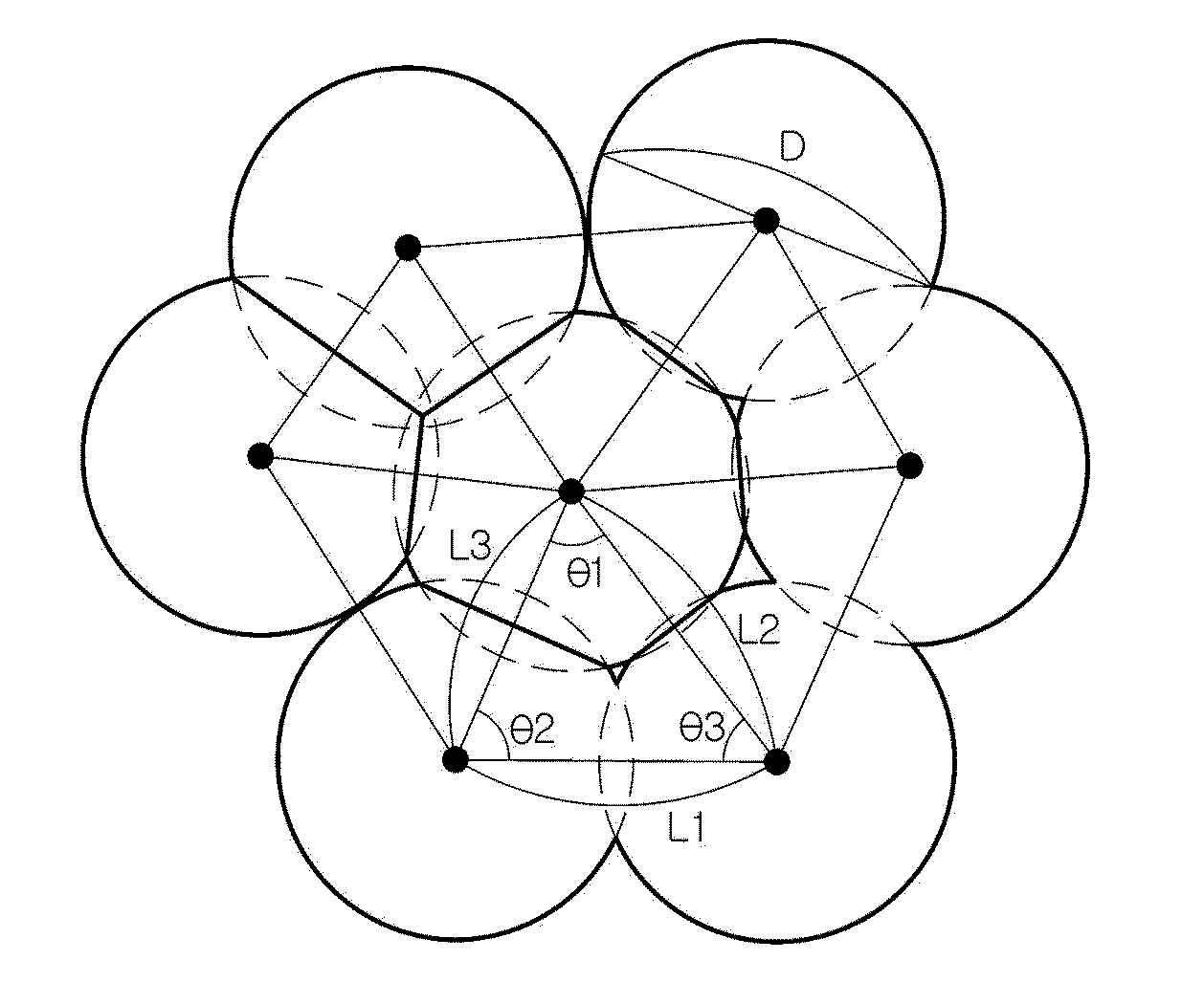
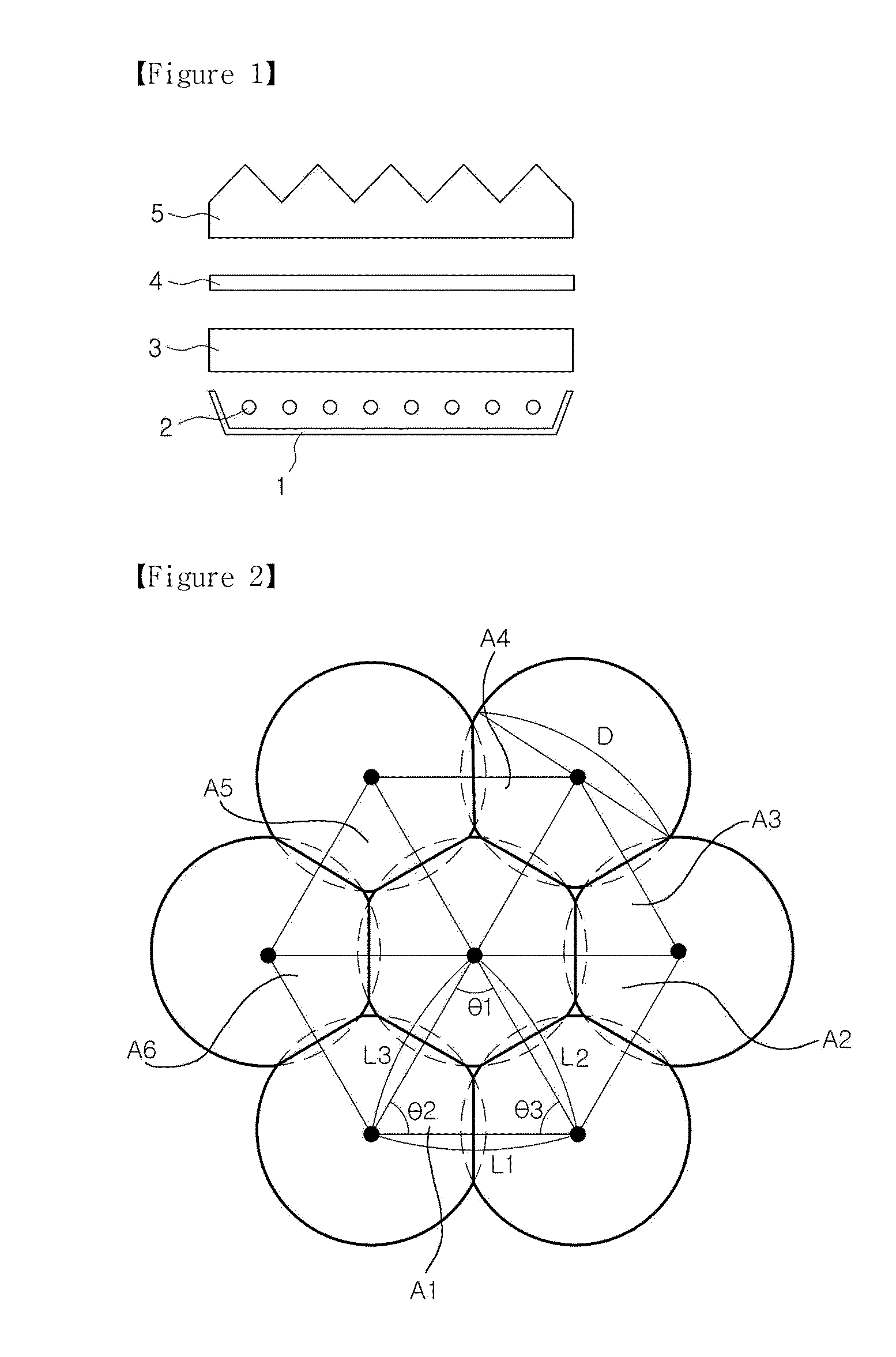
However, if micro lenses are periodically arranged on the MLA sheet as shown in FIG. 2, when the MLA sheet is superposed on another optical sheet having a periodic arrangement or pattern or an LCD panel having periodic pixels, a moiré pattern may occur due to geometric interference.
However, such hemispheric micro-lens array sheets have limitations in improving brightness and result in decreases in brightness when increasing viewing angles.
Method used
View moreImage
Smart ImageViewing Examples
Examples
example 2
[0062]Condensing film having two-dimensionally arranged micro conic lenses was formed under the same conditions as those of Example 1 except that: standard deviation in distances between the centers of any two neighboring conic lenses=9.2 μm, and area variation of triangular basic array units=18.5%.
Login to View More PUM
 Abstract
The present invention relates to a microlens array sheet with enhanced optical performance, and a backlight unit having same, and more specifically, to a microlens array sheet and a backlight unit having same, the microlens array sheet comprising: a base portion; and a plurality of microlenses formed on one surface of the base portion, wherein the plurality of microlenses have an irregular array, and the standard deviation of the distance between the mid points of two microlenses adjacent to each other is, 2-20% of the average pitch(p) between microlenses adjacent from the mid point of a selected microlens after selecting one of the microlenses.
Description
TECHNICAL FIELD[0001]The present invention relates to a micro-lens array sheet and a backlight unit including the micro-lens array sheet, and more particularly, to a micro-lens array sheet on which micro lenses are arranged so as to reduce moiré patterns and improve optical characteristics and a backlight unit including the micro-lens array sheet.BACKGROUND ART[0002]Liquid crystal display devices are electronic devices for converting electrical signals generated from various devices into visual information by using variations in the transmissivity of liquid crystals caused by a voltage applied thereto. Owing to merits such as small size, light weight, and low power consumption, liquid crystal display devices have been considered substitutes for cathode ray tubes (CRTs) and are now used in most information processing apparatuses requiring display devices.[0003]In such a liquid crystal display device, a voltage is applied to liquid crystals to change the molecular arrangement thereof ...
Claims
Login to View More Application Information
Patent Timeline
 Patent Type & Authority Applications(United States)
IPC IPC(8): G02B3/00
CPCG02B3/0043G02B3/0031G02B3/0062G02B3/00G02B5/02G02F1/1335
Inventor KIM, YUNE-HYOUNHAN, SANG-CHOLL
Owner LG CHEM LTD
Features
- R&D
- Intellectual Property
- Life Sciences
- Materials
- Tech Scout
- Unparalleled Data Quality
- Higher Quality Content
- 60% Fewer Hallucinations
Learn More Browse by: Latest US Patents, China's latest patents, Technical Efficacy Thesaurus, Application Domain, Technology Topic, Popular Technical Reports.
© 2025 PatSnap. All rights reserved.Legal|Privacy policy|Modern Slavery Act Transparency Statement|Sitemap|About US| Contact US: help@patsnap.com


