Microwave assisted magnetic recording and magnetic storage device

a technology of magnetic recording and magnetic storage device, which is applied in the direction of magnetic recording head, data recording, instruments, etc., can solve the problems of deterioration in error rate, production of magnetic storage device, and degraded servo quality

Active Publication Date: 2013-12-19
HITACHI LTD
View PDF4 Cites 48 Cited by
  • Summary
  • Abstract
  • Description
  • Claims
  • Application Information

AI Technical Summary

Problems solved by technology

This makes it increasingly difficult to perform recording using a current perpendicular magnetic recording head.
Especially a perpendicular magnetic recording medium has distribution in magnetic properties in the circumferential direction as described in JP 2010-231866 A and JP 2006-73176 A, and if a perpendicular magnetic recording medium has an insufficient recording area or a weak write area, such a perpendicular magnetic recording medium in combination with a magnetic head of poor recording ability causes a big problem during mass production of magnetic storage devices.
That is, problems such as degraded servo quality and deterioration in error rate occur at such an area, and an attempt to perform recording at this area will lead to recording at an easy-recording area with excessive magnetic field intensity, and so will fail to achieve high TPI by shortening the distance between recording tracks because of adjacent track write (ATW) or adjacent track erase (ATE) by side recording or side erasing.
However, when the device is operated in low-temperature environment, a problem of the weak write will occur at an area beyond the recording ability of the recording head, and in high-temperature environment, a problem of the ATE or the ATW will occur, and so design margin of magnetic heads and magnetic storage devices is very limited, thus causing problems of lower manufacturing yield of magnetic heads and magnetic storage devices.
Such a proposal, however, has a problem of low performance because it always takes extra time to access an appropriate area during recording / reproducing.
Such an attempt, however, causes a problem about reliability because heat generated at a magnetic core increases with the recording current intensity, thus making a magnetic pole protrude and so increasing the frequency of contact with the perpendicular magnetic recording medium.
Another attempt has been made using a clearance controller (TFC: Thermal Fly Height Controller) based on thermal expansion, and such an attempt also has a problem that the control is very difficult due to different time constants of clearance response and irregular variation of the clearance induced, and so durability reliability is further degraded.
This problem may be alleviated by increasing the average clearance, which also is not favorable because of deterioration in error rate.
Thus a perpendicular magnetic recording medium having an area where errors are concentrated, i.e., a sector having a poor error rate is the big problem to achieve better yield.

Method used


Image

  • Microwave assisted magnetic recording and magnetic storage device
  • Microwave assisted magnetic recording and magnetic storage device
  • Microwave assisted magnetic recording and magnetic storage device

Examples


embodiment 1

[0061]The following describes embodiments of a microwave assisted magnetic recording head and a magnetic storage device of the present invention, with reference to the drawings.

(Microwave Assisted Magnetic Recording Head)

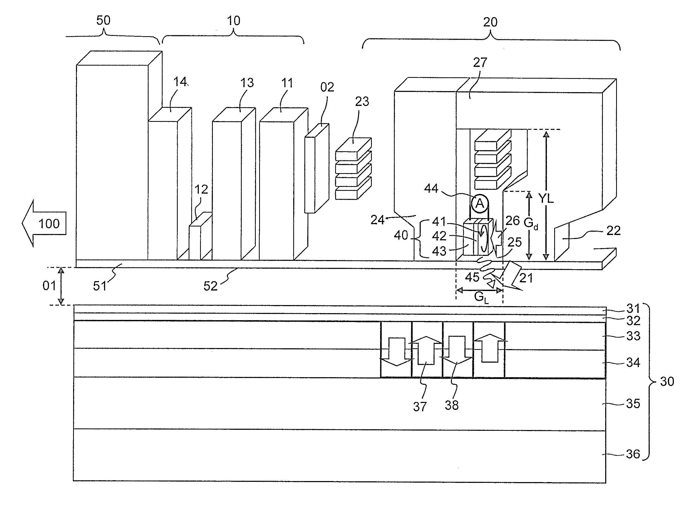
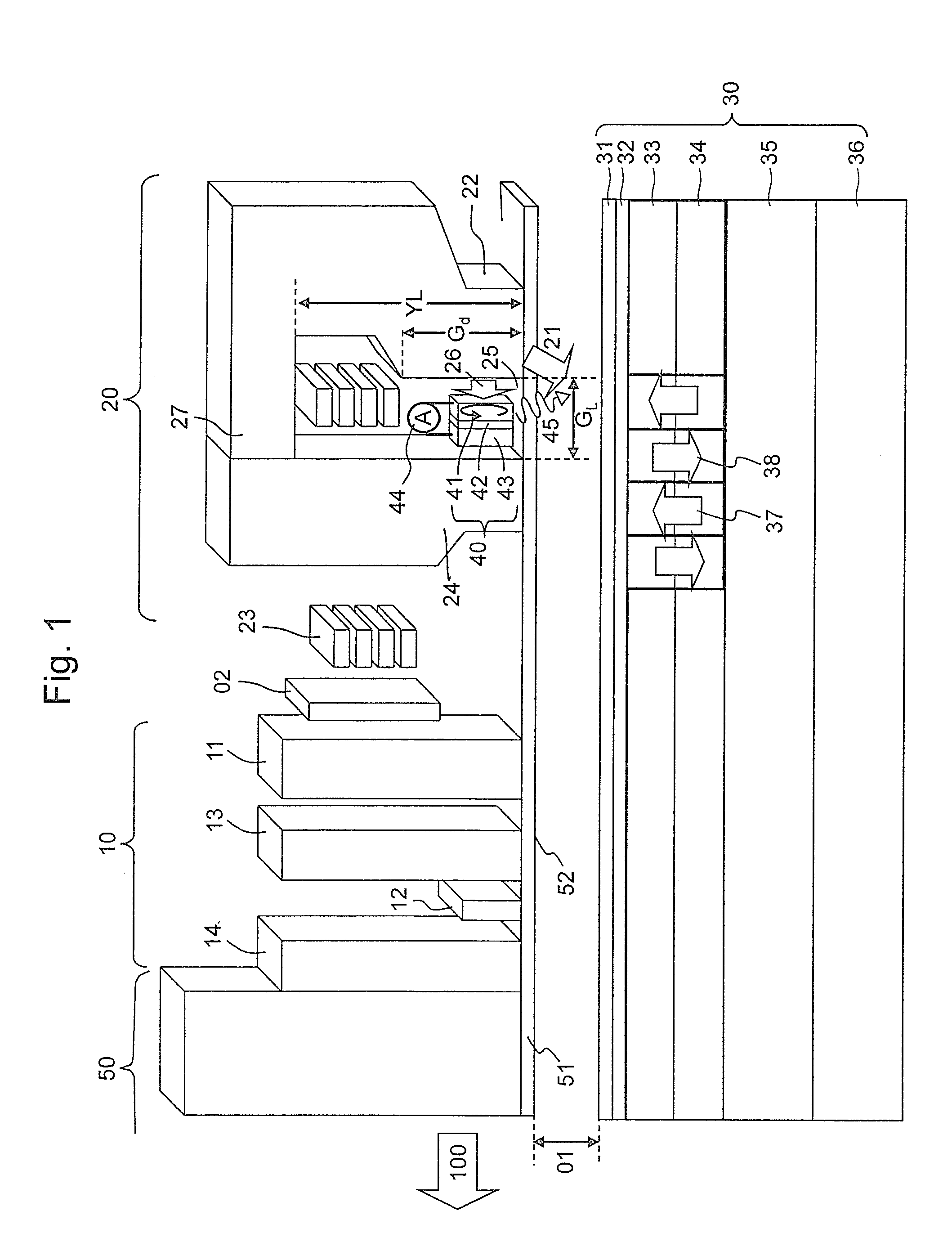
[0062]FIG. 1 is a conceptual diagram showing an exemplary microwave assisted magnetic recording head and such a perpendicular magnetic recording medium. A magnetic head includes a reproducing head part 10, a recording head part 20 and a thermal expansion element (TFC) 02 for clearance control or the like formed on a slider 50 traveling in the direction of an arrow 100 while keeping clearance 01 over a perpendicular magnetic recording medium 30. Herein, the TFC 02 includes a heat-generation resistive element thin film of about 50 to 150Ω made of a material having high specific resistance and a high thermally expandable property, such as NiCr or W and insulated with alumina film, and has a function of adjusting the clearance between the recording head part 20 or the r...

embodiment 2

[0130]FIGS. 17, 18 and 19 are schematic cross-sectional views of a magnetic head and a perpendicular magnetic recording medium in a magnetic storage device provided with a microwave assisted magnetic recording head of the present embodiment. The details are as follows:

[0131](1) Structure of a magnetic storage device shown in FIG. 17

[0132]slider 50: thin long femto type (1×0.7×0.2 mm)

[0133]head protective film (FCAC): 1.8 nm

[0134]sensor element 12: TMR (Twr=30 nm)

[0135]first magnetic recording pole 22: FeCoNi (Tww=100 nm, 80 nm)

[0136]STO 40: CoFeGe (10 nm) / Cu (2.5 nm) / Co / Ni (10 nm)

[0137]FGL width: WFGL=36 nm

[0138]medium substrate: 3.5-inch NiP plated Al alloy substrate

[0139]medium structure: lubricant film (1 nm) / C (2 nm) / CoCrPt(SiTi)O2 (2 nm) / CoCrPtSiO2C (10 nm) / Ru (10 nm) / CoFeTaZr (10 nm) / Ru(0.5 nm) / CoFeTaZr (10 nm)

[0140](2) Structure of a magnetic storage device shown in FIG. 18

[0141]slider 50: femto type (0.85×0.7×0.23 mm)

[0142]head protective film (FCAC):1.4 nm

[0143]sensor eleme...

embodiment 3

[0165]Referring to FIGS. 22 and 23, the following describes an embodiment using a microwave assisted magnetic recording head having another configuration. FIG. 22 schematically shows a cross-section of a microwave assisted magnetic recording head of the present embodiment and a perpendicular magnetic recording medium, and FIG. 23 schematically shows a recording head part viewed from the ABS face.

(Microwave Assisted Magnetic Recording Head)

[0166]The microwave assisted magnetic recording head of the present embodiment basically has the same configuration as those of Embodiments 1 and 2 (FIG. 1) except for the magnetic recording pole. In the drawing, it includes a slider 50, a head protective layer 51, a floating face 52, a STO 40, a reproducing head part 10, a shield layer 11, a reproduction sensor element 12, upper and lower magnetic shields 13 and 14 and TFC element 02a and 02b and the like.

[0167]As shown in FIG. 23 that is a structure of a magnetic pole part viewed from the ABS fac...


PUM

PropertyMeasurementUnit
specific resistanceaaaaaaaaaa
lengthaaaaaaaaaa
heightaaaaaaaaaa

Abstract

Disclosed is a technique of providing a large-capacity magnetic storage device at high device manufacturing yield while keeping the reliability, the magnetic storage device enabling recording on a perpendicular magnetic recording medium having distribution of characteristics in the circumferential direction as well at high track density of 500 kTPI or more that would be expected from the average characteristics of the medium. A recording condition from is selected for each sector from a parameter table that stores a set of at least two types of recording conditions by a microwave assisted magnetic recording head including a magnetic recording pole and a high-frequency magnetic field oscillator in the magnetic storage device, and information is recorded for each sector based on the condition.

Description

CLAIM OF PRIORITY[0001]The present application claims priority from Japanese patent application JP 2012-137210 filed on Jun. 18, 2012, the content of which is hereby incorporated by reference into this application.BACKGROUND OF THE INVENTION[0002]1. Field of the Invention[0003]The present invention relates to a magnetic storage device equipped with a function of assisting magnetization reversal of a perpendicular magnetic recording medium by applying high-frequency magnetic field, and a method for controlling the same.[0004]2. Background Art[0005]The growth of the Internet environment and newly provided data centers along with penetration of cloud computing have increased the amount of information generated in recent years. There is no doubt that magnetic storage devices such as magnetic disk devices (HDD) having the highest recording density and excellent bit cost play the leading role for storage in the “age of big data”. To this end, magnetic storage devices have to have larger c...

Claims


Application Information

Patent Timeline
Patent Type & Authority Applications(United States)
IPC IPC(8): G11B5/127
CPCG11B5/1278G11B5/02G11B2005/0024G11B2005/001G11B5/607
Inventor SHIROISHI, YOSHIHIRO
Owner HITACHI LTD
Why Eureka
Try Eureka