Optical fiber and composite inorganic ferrule assemblies and methods

a technology of inorganic ferrules and optical fibers, applied in the direction of glass making apparatus, manufacturing tools, instruments, etc., can solve the problems of difficult to achieve repeatable quality in the adhesive bond, limited pot life after mixing, undesired long curing time after application, etc., to achieve excellent dimensional stability and limited pot life

Inactive Publication Date: 2013-12-19
CORNING OPTICAL COMM LLC
View PDF5 Cites 3 Cited by
  • Summary
  • Abstract
  • Description
  • Claims
  • Application Information

AI Technical Summary

Benefits of technology

[0003]Fiber and ferrule assemblies are typically formed by securing a glass fiber within a ceramic ferrule by any of various methods, but one of the most common is by use of an epoxy-based adhesive. The ceramic of the ferrule constitutes a relatively tough material with excellent dimensional stability and generally somewhat customizable CTE. While use of epoxy is generally an inexpensive approach, there are significant disadvantages, including the difficulty of achieving repeatable quality in the adhesive bond, typically requiring careful inspection, cold storage, precise mixing, degassing, and careful dispensing of the epoxy. Limited pot life after mixing and undesirably long curing times after application are additional disadvantages of epoxy.

Problems solved by technology

While use of epoxy is generally an inexpensive approach, there are significant disadvantages, including the difficulty of achieving repeatable quality in the adhesive bond, typically requiring careful inspection, cold storage, precise mixing, degassing, and careful dispensing of the epoxy.
Limited pot life after mixing and undesirably long curing times after application are additional disadvantages of epoxy.

Method used


Image

  • Optical fiber and composite inorganic ferrule assemblies and methods
  • Optical fiber and composite inorganic ferrule assemblies and methods
  • Optical fiber and composite inorganic ferrule assemblies and methods

Examples


Embodiment Construction

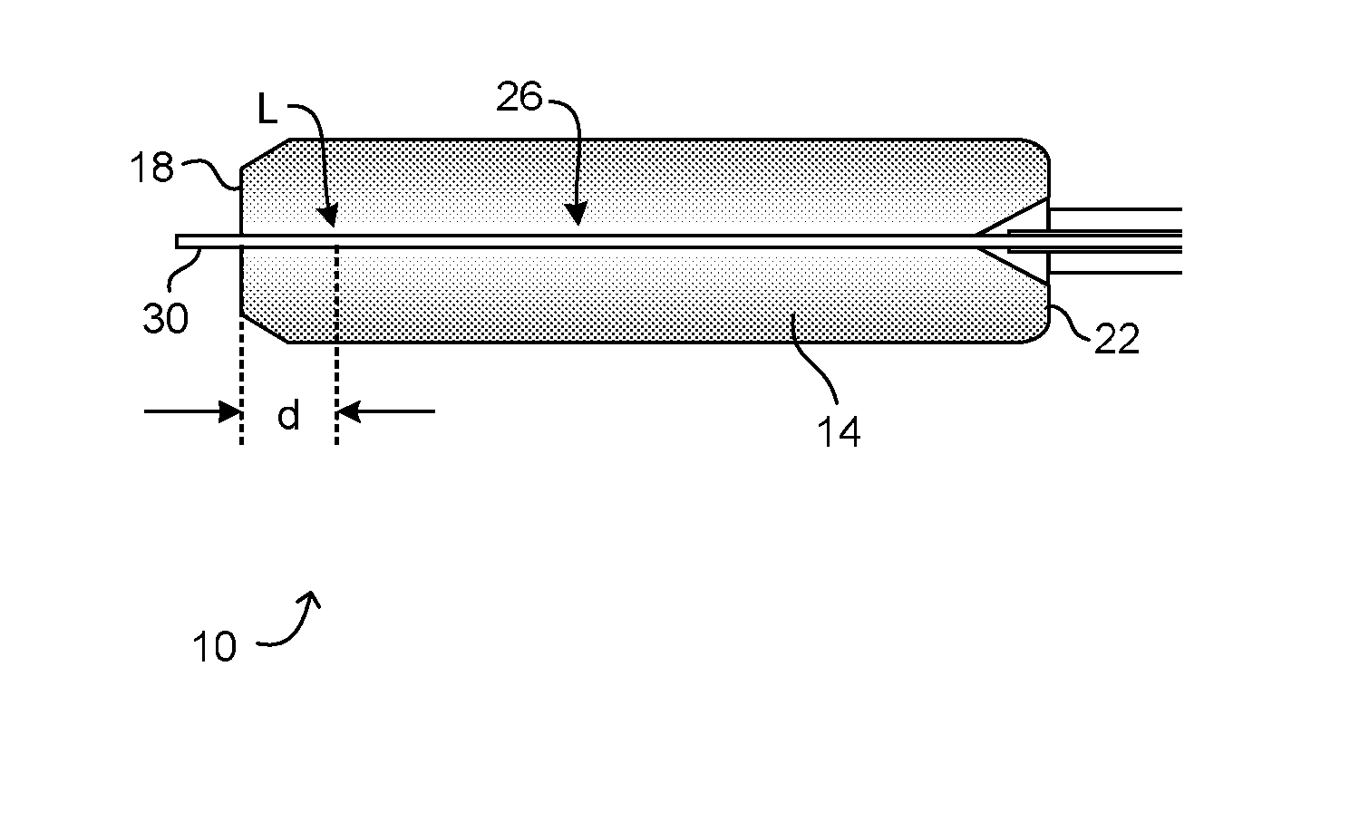
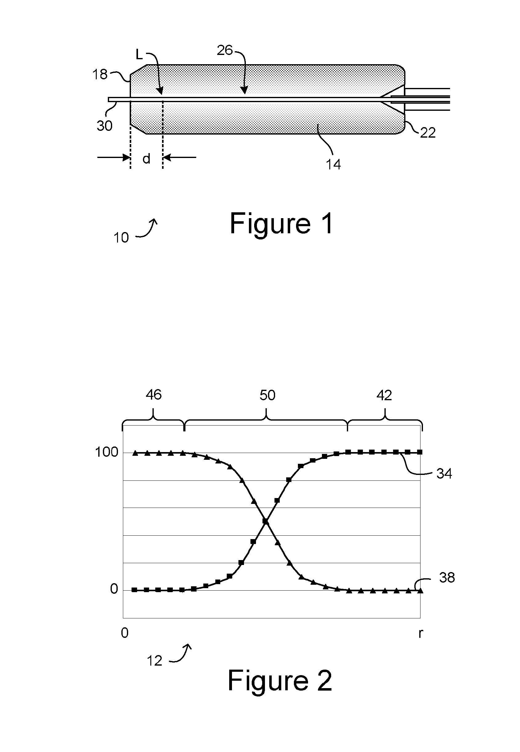
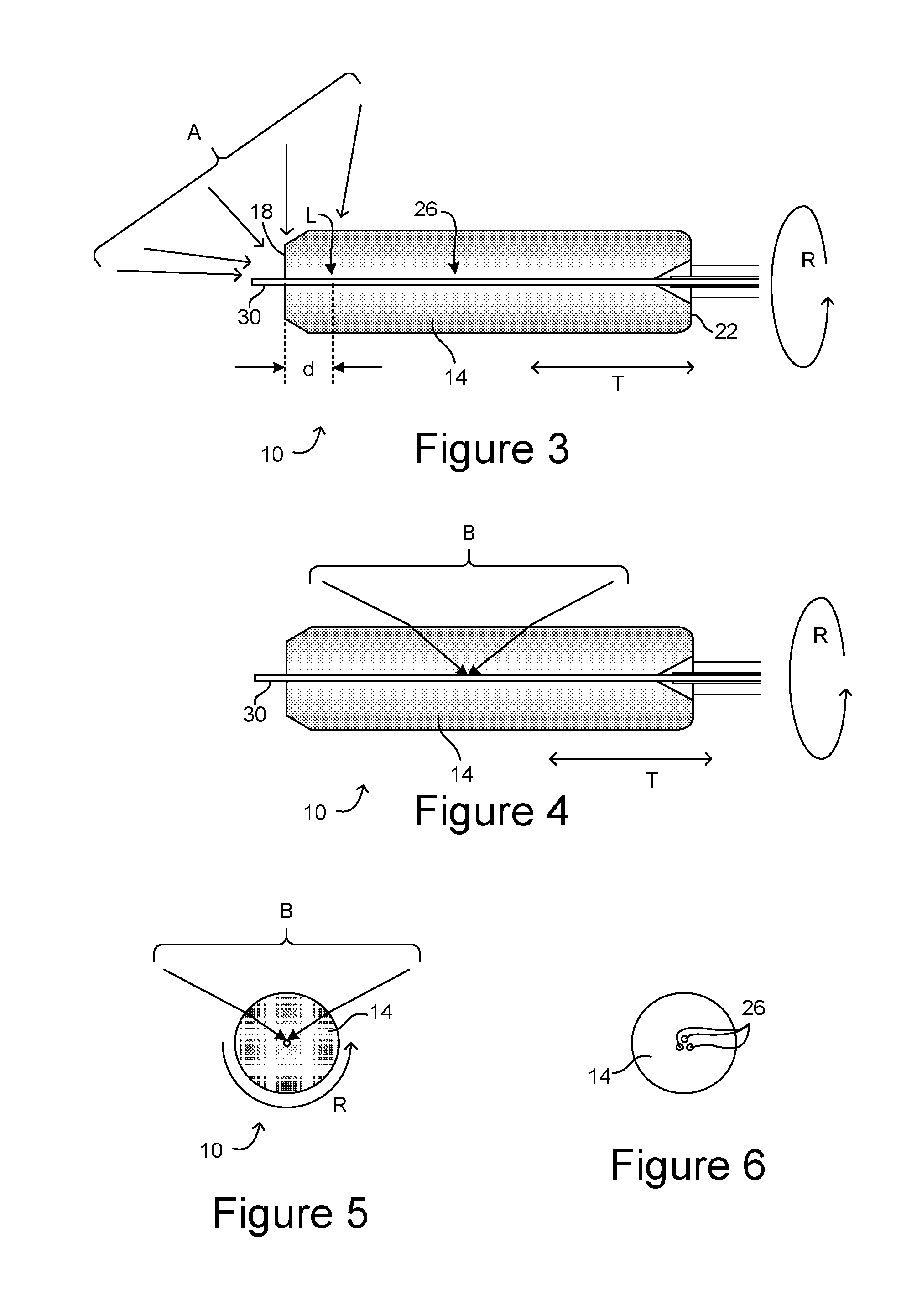
[0013]According to one aspect of the present disclosure, and with particular reference to the cross-sectional diagram of FIG. 1, a pre-terminated optical fiber assembly 10 comprises a ferrule 14 having front and rear opposed faces 18, 22 and at least one fiber bore 26 defined longitudinally therethrough. A glass optical fiber 30 is disposed within the at least one fiber bore 26 of the ferrule 14. The fiber 30 is fused (e.g., merged / melted together; blended to form a single entity) to the ferrule 14 at a location L at least 1 mm deep inside the at least one fiber bore 26, or in other words, at a location L which is a distance d from the front face 18 of the ferrule 14, where d is at least 1 mm (e.g., at least 2 mm, at least 5 mm) The ferrule 14 is composed of an inorganic composite material, the composite comprising a material gradient from at least 75% by volume of a first inorganic material to at least 75% by volume of second inorganic material in the radially inward direction, the...


PUM

PropertyMeasurementUnit
softening pointaaaaaaaaaa
distanceaaaaaaaaaa

Abstract

A pre-terminated optical fiber assembly with a ferrule having front and rear opposed faces and at least one fiber bore defined longitudinally therethrough includes a glass optical fiber is disposed within the at least one fiber bore with the fiber fused to the ferrule at a location at least 1 mm deep inside the bore. A method for fusing is also disclosed. The ferrule 14 is desirably composed of an inorganic composite material, the composite comprising a material gradient from at least 75% by volume of a first inorganic material to at least 75% by volume of second inorganic material in the radially inward direction, where the first inorganic material has a fracture toughness of at least 1 MPa•m1/2, and the second inorganic material has a softening point of no greater than 1000° C., desirably no greater than 900° C.

Description

RELATED APPLICATIONS[0001]This application claims the benefit of priority under 35 U.S.C. §119 of U.S. Provisional Application Ser. No. 61 / 660,235 filed on Jun. 15, 2012, the content of which is relied upon and incorporated herein by reference in its entirety.FIELD[0002]The present disclosure relates to optical fiber and ferrule assemblies and methods for assembling optical fibers and ferrules together, and particularly to optical fiber and composite inorganic ferrule assemblies and methods for assembling optical fibers with together with composite inorganic ferrules.BACKGROUND AND SUMMARY[0003]Fiber and ferrule assemblies are typically formed by securing a glass fiber within a ceramic ferrule by any of various methods, but one of the most common is by use of an epoxy-based adhesive. The ceramic of the ferrule constitutes a relatively tough material with excellent dimensional stability and generally somewhat customizable CTE. While use of epoxy is generally an inexpensive approach, ...

Claims


Application Information

Patent Timeline
Patent Type & Authority Applications(United States)
IPC IPC(8): G02B6/36
CPCG02B6/36G02B6/3855G02B6/3854G02B6/3861
Inventor DANLEY, JEFFREY DEANELKINS, II, ROBERT BRUCE
Owner CORNING OPTICAL COMM LLC
Why Eureka
Try Eureka