Pouch cell comprising an empty-volume defining component

a technology of defining components and pouches, which is applied in the direction of cell components, cell component details, secondary cell servicing/maintenance, etc., can solve the problems of gaseous product adversely affecting cell performance, and achieve the effect of reducing the length of the pouch bulging as a result of gas produced inside the pouch

Inactive Publication Date: 2013-12-19
ETV ENERGY LTD
View PDF3 Cites 34 Cited by
  • Summary
  • Abstract
  • Description
  • Claims
  • Application Information

AI Technical Summary

Benefits of technology

[0017]According to an aspect of some embodiments of the invention, a pouch cell, such as a lithium-ion chemistry pouch cell, is provided where a portion of the inner volume of the pouch is substantially empty and the pressure inside the pouch is subatmospheric. In some embodiments, the substantially empty portion is such that at least some of a gas produced inside the pouch, for example due to decomposition of components of the electrolyte, is accommodated in the substantially empty portion of the inner

Problems solved by technology

In some such embodiments, such decomposition of electrolyte to form a gaseous product adversely affects cell performance to

Method used


Image

  • Pouch cell comprising an empty-volume defining component
  • Pouch cell comprising an empty-volume defining component
  • Pouch cell comprising an empty-volume defining component

Examples


embodiment 32

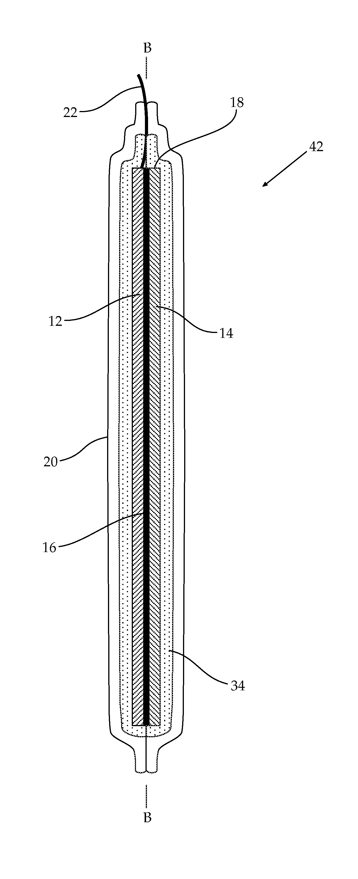
[0134]An embodiment 32 of a pouch cell in accordance with the teachings herein is schematically depicted in FIG. 2 in longitudinal (B-B) cross section.

[0135]Pouch cell 32 comprises a rectangular flexible shell in the form of a sealed pouch 20 (outer dimensions 30 cm by 20 cm) of heat-sealable laminated foil, inside which is contained a flat planar laminated electrode assembly 18 including a positive electrode layer 12, a negative electrode layer 14, a separator layer 16, an empty-volume defining component 34 and an amount of electrolyte such that a portion of the inner volume of pouch 20 is substantially empty. The pressure inside pouch 20 is subatmospheric, for example at a pressure determined by the vapor pressure of components of the electrolyte.

[0136]Positive contact 22 is functionally associated with positive electrode layer 12 and passes through a seam in pouch 20 so as to be apparent on the outside of pouch 20. A negative contact is functionally associated with negative elect...

embodiment 38

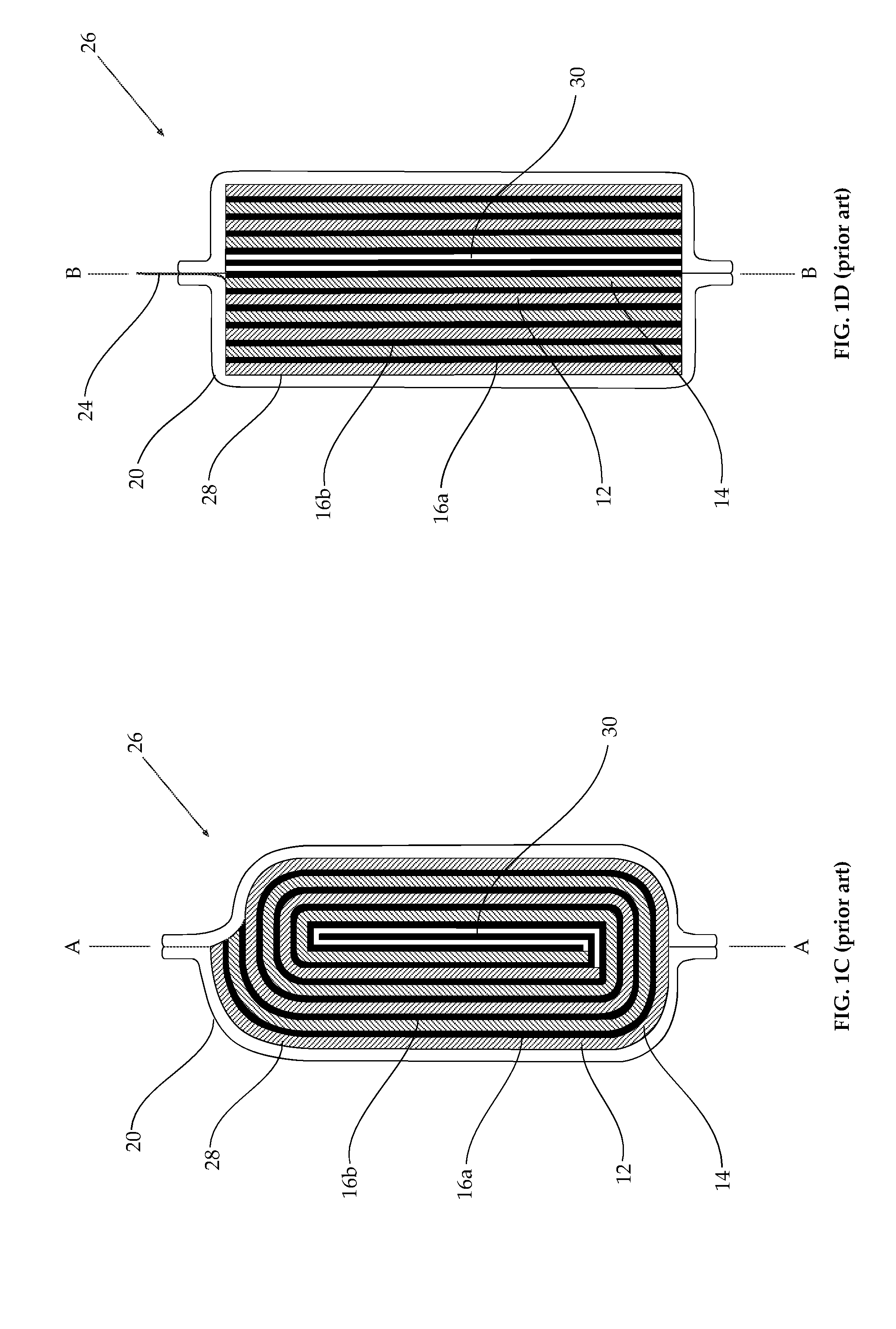
[0144]An additional embodiment 38 of a pouch cell in accordance with the teachings herein is schematically depicted in transverse cross section (A-A) in FIG. 3A and in longitudinal cross section (B-B) in FIG. 3B. Pouch cell 38 comprises a spiral laminated electrode assembly 28 and an empty-volume defining component 34 made of a single porous sheet of 300 micrometer mesh having a 70% porosity of woven polypropylene fibers. Empty-volume defining component 34 is longer than electrode assembly 28 and is wound about electrode assembly 28 so as to envelop electrode assembly 28.

[0145]In pouch cell 38, the ends of the porous sheet constituting empty-volume defining component 34 abut. In some similar embodiments, the ends of a porous sheet wound about an electrode assembly overlap to constitute an empty-volume defining component. In some similar embodiments, a porous sheet is wound so as to be spirally wound around an electrode assembly to constitute an empty-volume defining component.

[0146]...

embodiment 40

[0147]An additional embodiment 40 of a pouch cell in accordance with the teachings herein is schematically depicted in longitudinal cross section (B-B) in FIG. 4. Pouch cell 40 comprises an empty-volume defining component 34 comprising a single porous sheet located on one side of and that does not envelop flat electrode assembly 18.


PUM


Abstract

Disclosed are pouch cells, for example lithium-ion pouch cells, where a portion of the inner volume of the pouch is substantially empty and there is subatmospheric pressure inside the pouch. In some embodiments gas released inside the pouch, for example during use of the cell, is accommodated in the substantially empty portion of the inner volume of the pouch, avoiding pouch bulging.

Description

FIELD AND BACKGROUND OF THE INVENTION[0001]The invention, in some embodiments, relates to the field of batteries and more particularly, but not exclusively, to pouch cells including a flexible shell.[0002]Traditional batteries include a rigid cylindrical shell of metal (often called a can) which defines the size and shape of the battery, and in some cases functions as an electrode or current collector.[0003]Recent developments in battery chemistry, particularly lithium-ion chemistry, allow greater flexibility in design of a battery shell such as the pouch cell described, for example, in U.S. Pat. Nos. 6,042,966; 6,048,638; 6,296,967; 6,337,154; U.S. patent application publication Nos. 2008 / 0254367, 2008 / / 0241671; 2008 / 0292962; 2008 / 0311469; 2009 / 0023062; 2009 / 0029245 and PCT patent publication WO 2006 / 073277.[0004]A pouch cell includes a flexible shell in the form of a pouch typically fashioned of a heat-sealable laminated foil. The pouch contains the electrodes and other cell-compo...

Claims


Application Information

Patent Timeline
IPC IPC(8): H01M10/52
CPCH01M10/52Y02E60/10H01M50/131H01M50/24
Inventor LUSKI, SHALOMMEITAV, ARIEH
Owner ETV ENERGY LTD
Why Eureka
Try Eureka