
Facilitating streaming fluid using acoustic waves

Inactive Publication Date: 2013-12-26
SEMATECH
View PDF3 Cites 10 Cited by
  • Summary
  • Abstract
  • Description
  • Claims
  • Application Information

AI Technical Summary

Benefits of technology

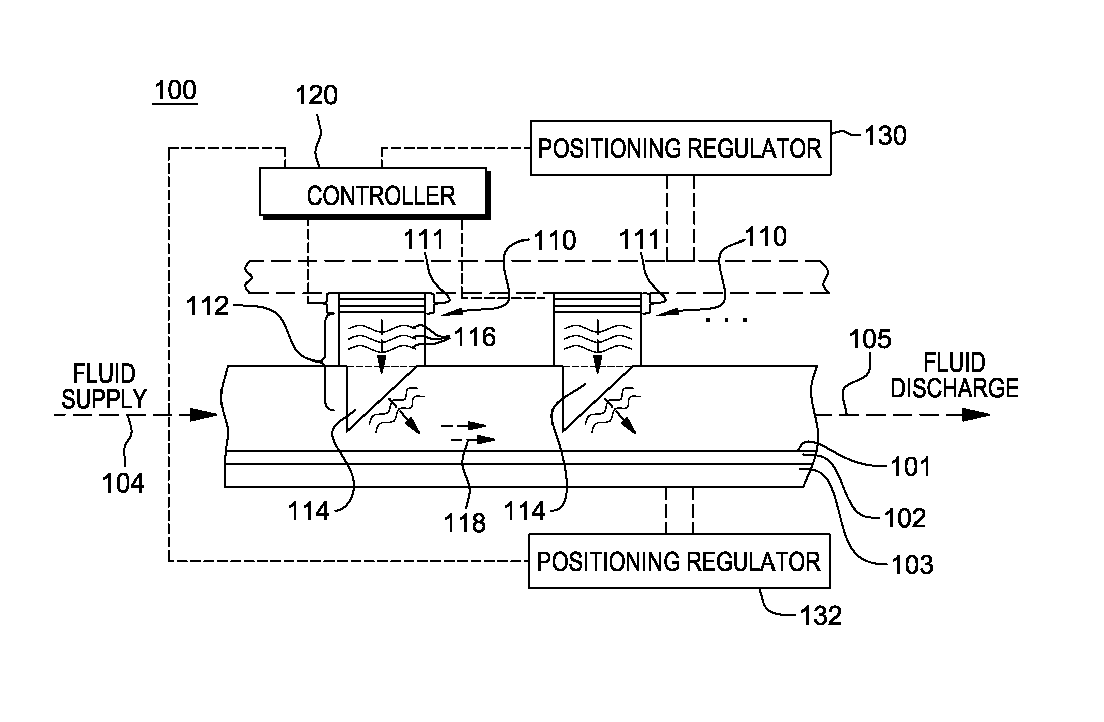
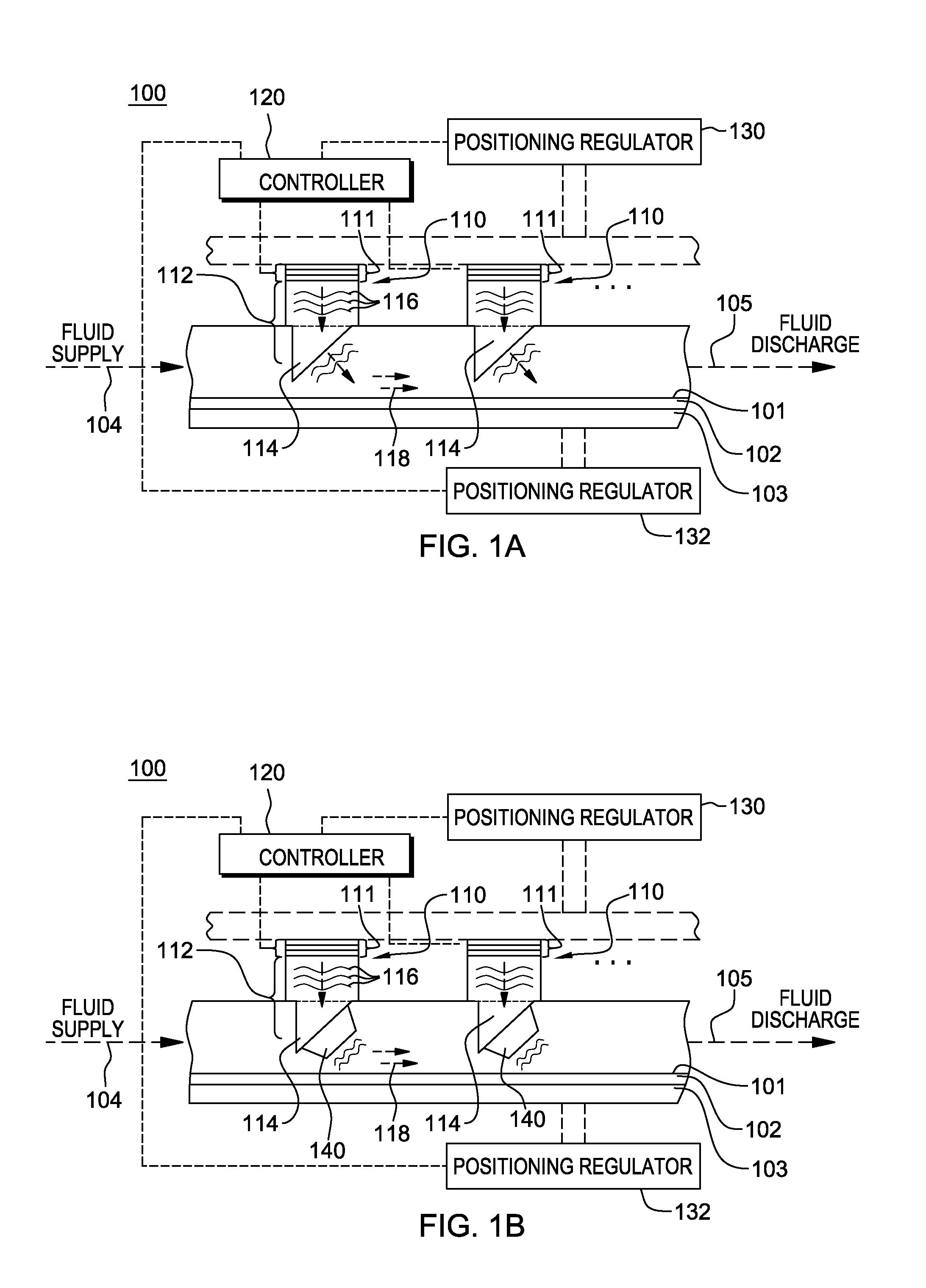
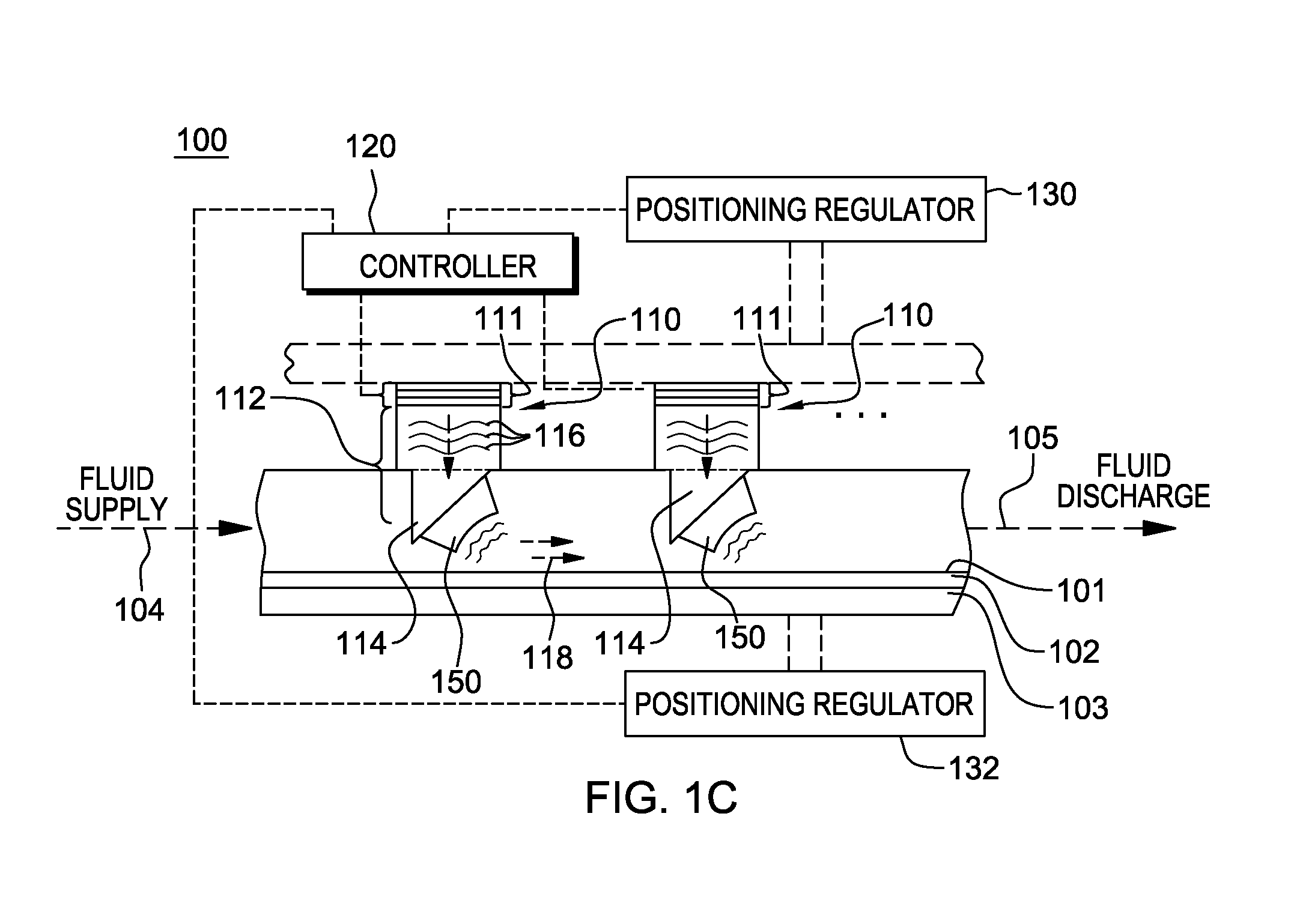
The present invention is about a system that uses acoustic waves to generate energy in a fluid. This system includes an acoustic wave generator and an acoustic coupler that helps to direct the waves into the fluid. The result is a flow of fluid that is directed and streamed in a common direction. The technical effect of this invention is improved and efficient energy conversion in fluids using acoustic waves.

Problems solved by technology

As understood in the art, incident light is scattered by rough surfaces, which can lead to the loss of intensity of the reflected light and to image deformation.
Removal of particles, such as sub-100 nanometer (nm) particles, from a surface can be a challenging subject in semiconductor fabrication processing.
Conventional wet-cleaning techniques that use under-etching of particles to remove particles from the surface result in undesirable roughening the surface, and thus, are no longer acceptable for today's semiconductor fabrication processes.
Other particles that are chemically bonded to a surface are more difficult to remove.
Unfortunately, close to the surface, there is a hydrodynamic boundary layer, which is a region immediately adjacent to the surface, with little or no flow.
This boundary layer may have a thickness of a micron or more, while the particle to be removed may be a nanometer-scaled particle, making it difficult to remove such particles from the surface using a conventional cleaning fluid flow approach.

Method used


Image

  • Facilitating streaming fluid using acoustic waves
  • Facilitating streaming fluid using acoustic waves
  • Facilitating streaming fluid using acoustic waves

Examples


Embodiment Construction

[0025]The invention and various features, advantageous and details thereof are explained more fully below with reference to the non-limiting embodiments illustrated in the accompanying drawings. Descriptions of well-known starting materials, processing techniques, components, and equipment, are omitted so as not to unnecessarily obscure the invention in detail. It should be understood, however, that the detailed description and the specific examples, while indicating embodiments of the invention, are given by way of illustration only, and are not by way of limitation. Various substitutions, modifications, additions, and / or rearrangements within the spirit and / or scope of the underlying inventive concepts will be apparent to those skilled in the art from this disclosure.

[0026]As noted, disclosed herein are certain novel acoustic wave systems and methods for facilitating a streaming flow of fluid. Generally stated, the acoustic wave systems disclosed herein include one or more acousti...


PUM


Abstract

Systems and methods are provided facilitating a steaming fluid flow utilizing acoustic waves. A system includes an acoustic wave generator and an acoustic coupler associated with the acoustic wave generator and coupling acoustic waves generated by the acoustic wave generator into a fluid. The acoustic coupler includes one or more acoustic coupling lenses, which direct the acoustic waves into the fluid and facilitate, at least in part, a streaming fluid flow in a common direction. In an enhanced embodiment, the common flow direction is at an angle to a direction acoustic waves are generated, and the acoustic coupling lens(es), in directing the acoustic waves into the fluid, redirects the acoustic waves from the direction of acoustic wave generation. The acoustic wave generator generates the acoustic waves in the megahertz or gigahertz range, for example, with a frequency of 20 MHz or higher.

Description

BACKGROUND[0001]Current semiconductor technology uses reflective optics, which require a surface roughness of, for example, approximately 1.5 angstrom RMS. As understood in the art, incident light is scattered by rough surfaces, which can lead to the loss of intensity of the reflected light and to image deformation.[0002]Removal of particles, such as sub-100 nanometer (nm) particles, from a surface can be a challenging subject in semiconductor fabrication processing. Surface-particle interactions depend on the material and the surface structure, and generally are size independent. To remove a particle from a surface, adhesive forces between the particle and the surface need to be broken, and the particle needs to be transported far enough away from the surface so that the particle will not be redeposited on the surface.[0003]Conventional wet-cleaning techniques that use under-etching of particles to remove particles from the surface result in undesirable roughening the surface, and ...

Claims


Application Information

Patent Timeline
IPC IPC(8): F15D1/02
CPCB08B3/12B08B2203/0288Y10T137/206Y10T137/0391
Inventor RASTEGAR, ABBAS
Owner SEMATECH
Learn More