
Touch panel

a technology of touch panel and mouse, which is applied in the direction of circuit electrical arrangement, printed circuit aspects, instruments, etc., can solve the problems of high cost, depletion of electrical conductivity, and difficulty in efficiently operating products using only a keyboard and a mouse currently serving as input devices, so as to reduce the trial and error of design of conductor lines, shorten the development period, and improve the effect of development efficiency

Inactive Publication Date: 2013-12-26
SAMSUNG ELECTRO MECHANICS CO LTD
View PDF2 Cites 39 Cited by
  • Summary
  • Abstract
  • Description
  • Claims
  • Application Information

AI Technical Summary

Benefits of technology

The present invention aims to provide a touch panel that can shorten the development period and increase efficiency by reducing trial and error in designing conductor lines and implementing higher quality using optimal design parameters.

Problems solved by technology

In accordance with the rapid advancement of an information-oriented society, the use of computers has gradually been widened; however, it is difficult to efficiently operate products using only a keyboard and a mouse currently serving as an input device.
However, the ITO has excellent electrical conductivity but is expensive since indium used as a raw material thereof is a rare earth metal.
In addition, the indium is expected to be depleted within the next decade, such that it may not be smoothly supplied.
However, in the case of the prior art, when the conductor line is made of the metal, there is a visibility problem that the conductor line is viewed by user's eyes, a moire problem generated by an interference between a display pattern and the conductor line or the like, such that commercialization is difficult.

Method used


Image

  • Touch panel
  • Touch panel
  • Touch panel

Examples


Embodiment Construction

[0046]The objects, features and advantages of the present invention will be more clearly understood from the following detailed description of the preferred embodiments taken in conjunction with the accompanying drawings. Throughout the accompanying drawings, the to same reference numerals are used to designate the same or similar components, and redundant descriptions thereof are omitted. Further, in the following description, the terms “first”, “second”, “one side”, “the other side” and the like are used to differentiate a certain component from other components, but the configuration of such components should not be construed to be limited by the terms. Further, in the description of the present invention, when it is determined that the detailed description of the related art would obscure the gist of the present invention, the description thereof will be omitted.

[0047]Hereinafter, preferred embodiments of the present invention will be described in detail with reference to the at...


PUM


Abstract

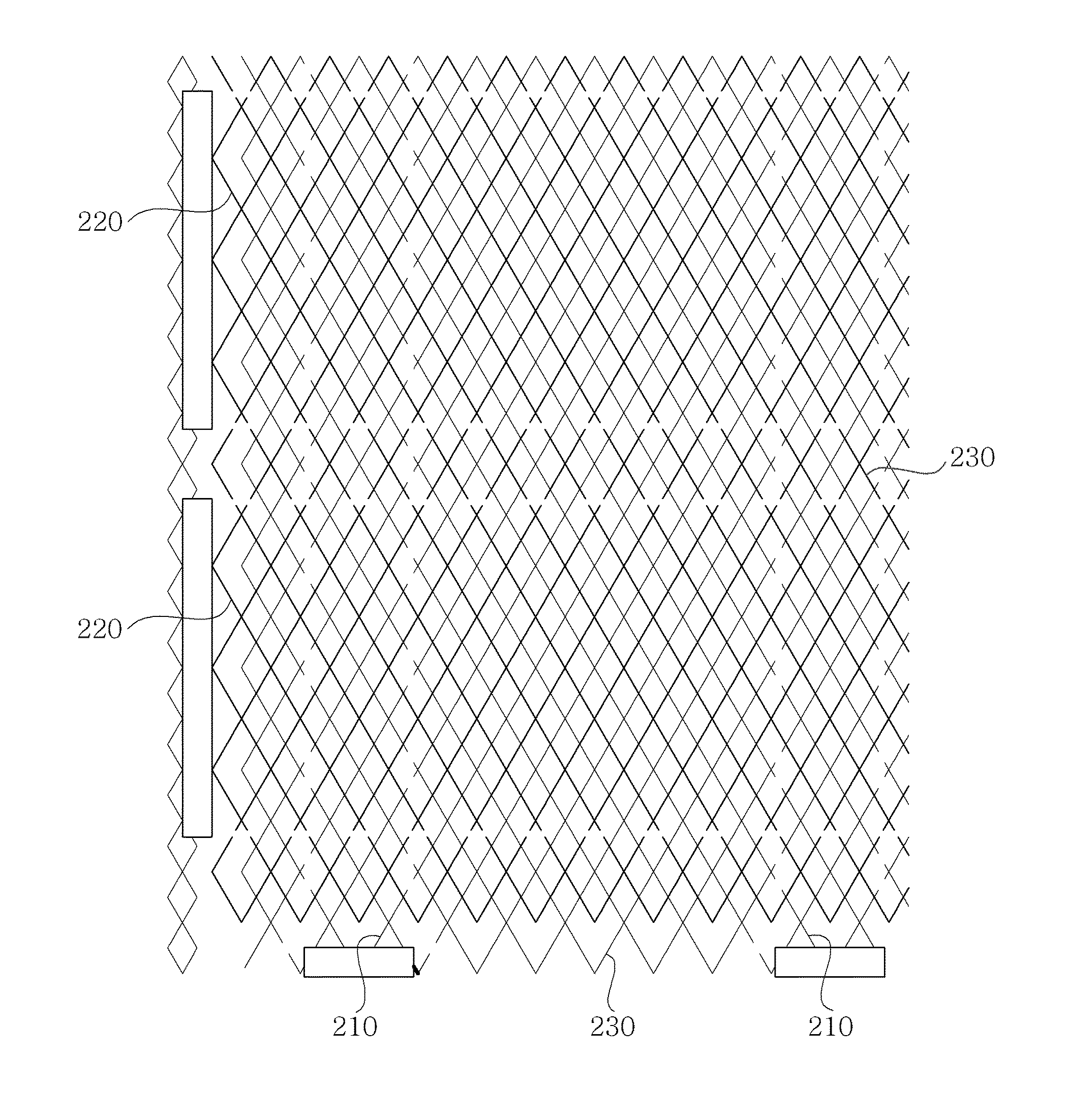
Disclosed herein is a touch panel, including: mesh conductor lines, wherein a pitch of the mesh conductor line has a value selected from pm=2×pd(fm=fd / 2, pm≦260 μm), wherein pm is a pitch of the mesh conductor line, pd is a pixel pitch of a display, fm is a frequency 1 / pm of the mesh conductor line, and fd is a pixel frequency 1 / pd of the display.

Description

CROSS REFERENCE TO RELATED APPLICATION[0001]This application claims the benefit of Korean Patent Application No. 10-2012-0068100, filed on Jun. 25, 2012, entitled “Touch Panel”, which is hereby incorporated by reference in its entirety into this application.BACKGROUND OF THE INVENTION[0002]1. Technical Field[0003]The present invention relates to a touch panel.[0004]2. Description of the Related Art[0005]In accordance with the growth of computers using a digital technology, devices assisting computers have also been developed, and personal computers, portable transmitters and other personal information processors execute processing of text and graphic using a variety of input devices such as a keyboard and a mouse.[0006]In accordance with the rapid advancement of an information-oriented society, the use of computers has gradually been widened; however, it is difficult to efficiently operate products using only a keyboard and a mouse currently serving as an input device. Therefore, th...

Claims


Application Information

Patent Timeline
Patent Type & Authority Applications(United States)
IPC IPC(8): H05K1/02
CPCH05K1/0213G06F2203/04112G06F3/0445G06F3/0446H05K1/11H05K2201/09681G06F3/044G06F3/041
Inventor KIM, HYUNYURLOV, VICTOR
Owner SAMSUNG ELECTRO MECHANICS CO LTD
Learn More