Downhole motor assembly

Active Publication Date: 2013-12-26
DRILFORMANCE TECH
View PDF4 Cites 7 Cited by
  • Summary
  • Abstract
  • Description
  • Claims
  • Application Information

AI Technical Summary

Benefits of technology

The patent text explains a way to separate loads in a machine, which allows for the use of separate thrust bearings for different parts of the machine. This results in better performance and more flexibility in the design of the machine.

Problems solved by technology

Radial loads experienced by a downhole motor may be due to side loading on components of the motor or transverse vibration of components of the motor.
Locating all of these bearings in the bearing section, and locating the bearing section below the drive connection may result in a relatively long distance between the drive connection and the distal end of the downhole motor.
This long distance is generally undesirable for several reasons.
First, a relatively long distance between the drive connection and the distal end of the motor results in a relatively long distance of the drive train between the power section and the drill bit.
This relatively long distance can result in earlier failure of a downhole motor in comparison with a downhole motor which has a relatively short distance between the power section and the drill bit, due to the effects of torque and torsion on the drive train.
As a result, a relatively long distance between the drive connection and the distal end of the motor provides a relatively long “bend to bit” distance.
A relatively long bend to bit distance is disadvantageous for directional drilling because a longer bend is inherently less stiff than a shorter bend, with the result that a bent downhole motor with a relatively short bend to bit distance tends to be able to provide a larger “build angle” than a bent downhole motor with a relatively long bend to bit distance.
Third, bent downhole motors may be used for non-directional drilling by rotating the drill string in addition to or in substitution for rotating the drill bit with the motor.
Rotation of the drill string rotates the motor, which results in rotation of the bend in the motor.
These side loads and bending moments may contribute to failure of the motor.
Although a large diameter borehole may be desirable in some circumstances, the use of a bent downhole motor with a relatively long bend to bit distance for non-directional drilling may be relatively inefficient in most circumstances.

Method used


Image

  • Downhole motor assembly
  • Downhole motor assembly
  • Downhole motor assembly

Examples


first embodiment

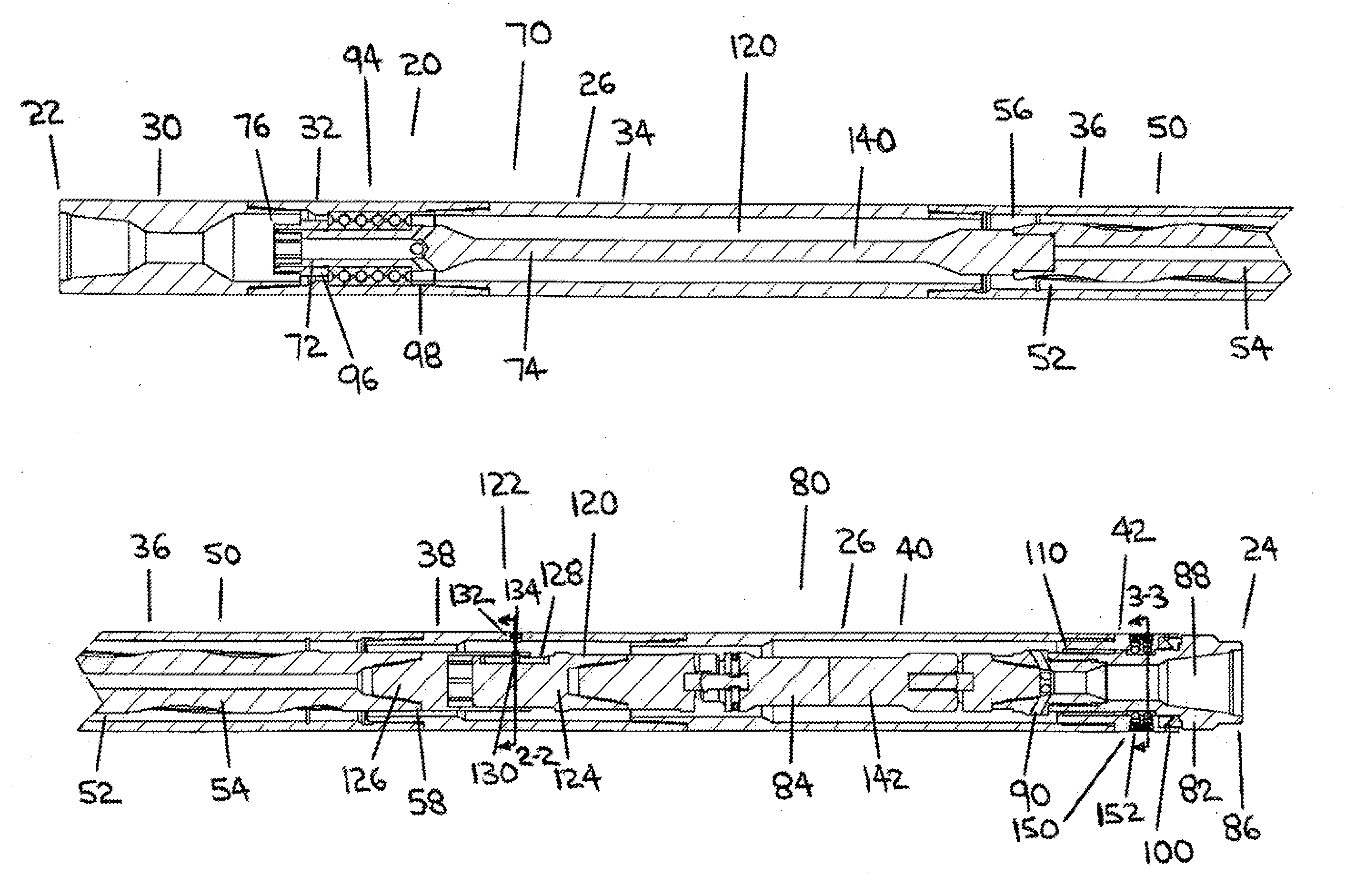
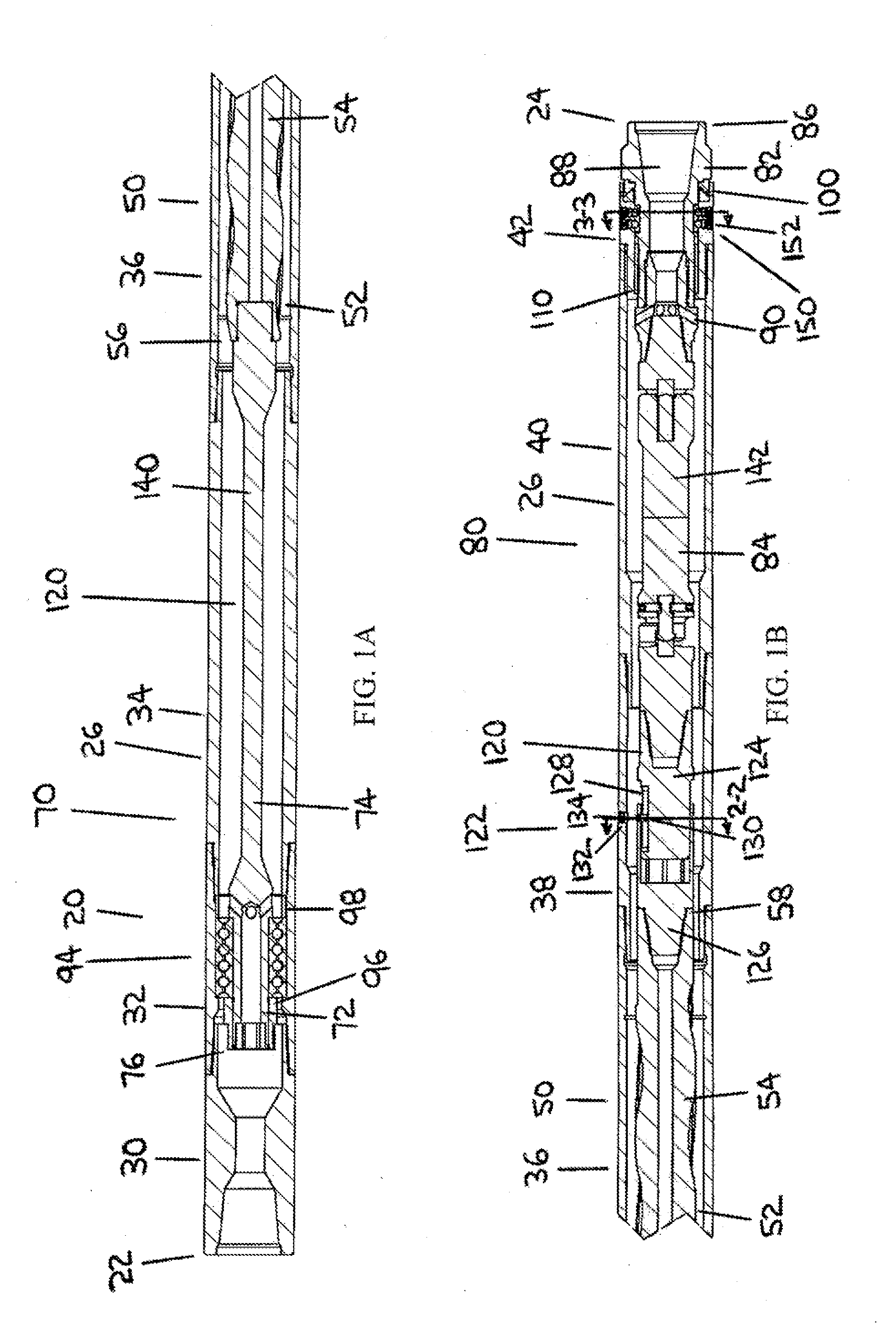
[0069]FIG. 1A and FIG. 1B are together a longitudinal section assembly view of the downhole motor assembly, in which the proximal drive connection is comprised of a flex shaft. FIG. 1A depicts the proximal end of the downhole motor assembly and FIG. 1B depicts the distal end of the downhole motor assembly. A portion of the power section of the downhole motor assembly has been omitted between FIG. 1A and FIG. 1B.

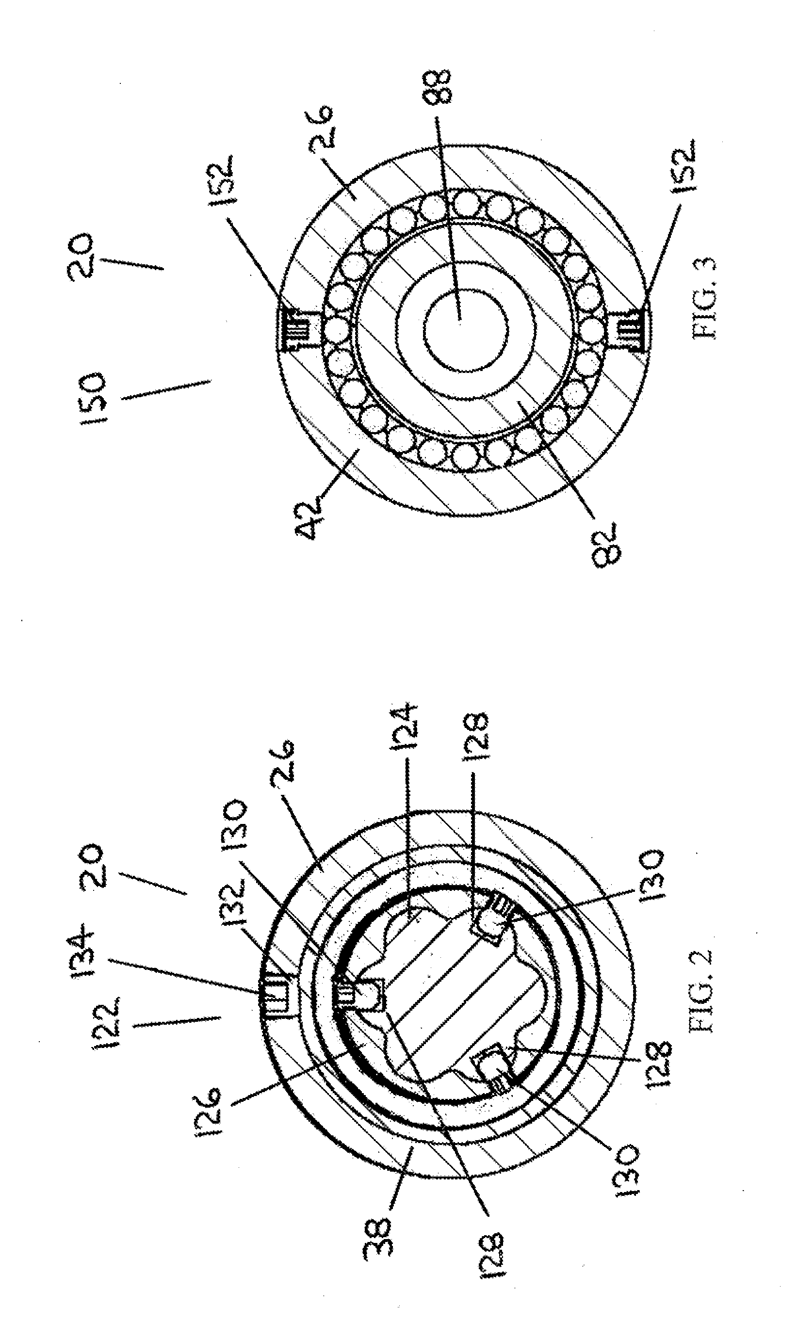
[0070]FIG. 2 is a transverse section view of the axial load decoupling device of the first embodiment of downhole motor assembly, in which the axial load decoupling device is comprised of a spline connection.

[0071]FIG. 3 is a transverse section view of the retainer bearing of the first embodiment of downhole motor assembly, in which the retainer bearing is comprised of two rolling element bearings.

second embodiment

[0072]FIG. 4A and FIG. 4B are together a longitudinal section assembly view of downhole motor assembly in which the proximal drive connection is comprised of a constant velocity coupling. FIG. 4A depicts the proximal end of the downhole motor assembly and FIG. 4B depicts the distal end of the downhole motor assembly. A portion of the power section of the downhole motor assembly has been omitted between FIG. 4A and FIG. 4B.

[0073]The first embodiment of downhole motor assembly and the second embodiment of downhole motor assembly depicted in FIGS. 1-4 represent two exemplary embodiments of the invention. Many other embodiments are possible within the scope of the invention as described herein.

[0074]In the description of the two exemplary embodiments which follows, features of the first embodiment of downhole motor assembly which are equivalent or identical to features of the second embodiment of downhole motor assembly are assigned the same reference number.

[0075]Referring to FIG. 1, a...


PUM


Abstract

A downhole motor assembly including a housing, a power section with a stator and a rotor contained within the housing, a proximal drive assembly connected with a proximal rotor end, a distal drive assembly connected with a distal rotor end, a proximal thrust bearing arranged between the housing and the proximal drive assembly, a distal thrust bearing arranged between the housing and the distal drive assembly, and an axial load decoupling device in the distal drive assembly located longitudinally between the distal rotor end and the distal thrust bearing, for separating axial loads imposed on the proximal thrust bearing from axial loads imposed on the distal thrust bearing.

Description

TECHNICAL FIELD A downhole motor assembly for use in drilling subterranean boreholes.BACKGROUND OF THE INVENTION[0001]Subterranean boreholes are typically drilled using a drill string which includes drill pipe or coiled tubing, with a drill bit connected at the distal end of the drill string.[0002]The drill bit may be rotated by rotating the entire drill string, and / or the drill bit may be rotated by a downhole motor which is included as a component of the drill string.[0003]A typical form of downhole motor is a progressing cavity motor. A progressing cavity motor includes a power section comprising a stator and a rotor received within the stator. Drilling fluid is passed through the power section of the downhole motor in order to convert fluid energy into rotational energy of the rotor within the stator. The rotor is typically connected indirectly with the drill bit via a drive shaft.[0004]In a progressing cavity motor, the rotor both rotates and nutates within the stator. As a res...

Claims


Application Information

Patent Timeline
IPC IPC(8): E21B4/00F16C17/02F16C17/04
CPCE21B4/003E21B4/02
Inventor GILLIS, SEAN
Owner DRILFORMANCE TECH
Why Eureka
Try Eureka