Cleaning head for floor cleaning device

Active Publication Date: 2006-03-30
ALFRED KARCHER GMBH & CO KG
View PDF15 Cites 2 Cited by
  • Summary
  • Abstract
  • Description
  • Claims
  • Application Information

AI Technical Summary

Benefits of technology

[0010] As a result of this, the coupling element transfers from its coupling position into a non-coupling position and the transfer of torque between the drive element and the driven element is interrupted. A limitation of the torque to be transferred is ensured by the overload coupling in a constructionally simple manner, wherein the critical limiting value of the torque can be predetermined by the spring force, with which the overload element is acted upon in the direction of rotation. In accordance with the invention, the overload element is arranged between the coupling element and the alternative space in a coupling position of the coupling element. This has the advantage that the access of the coupling element to the alternative space is blocked by the overload element and is released when an overload occurs. The overload coupling is therefore characterized by a reliable mode of operation.
[0011] In a preferred embodiment, the alternative space adjoins the intermediate space radially on its outer side. Since the coupling element, like the drive element and the driven element, executes a rotational movement during the transfer of torque, the arrangement of the alternative space on the radially outer side has the advantage that the transfer of the coupling element into the alternative space can be achieved by means of the centrifugal force acting on the coupling element. The arrangement of the alternative space on the radially outer side also has the advantage that the at least one coupling element is held automatically in the alternative space when an overload occurs on account of the centrifugal force acting on the coupling element without additional retaining elements needing to be used for this purpose.
[0017] It has proven to be favorable when the torsion spring can be releasably connected to the drive element or driven element. This makes it possible, depending on the desired limiting value for the torque to be transferred, to use a torsion spring adapted to this limiting value.
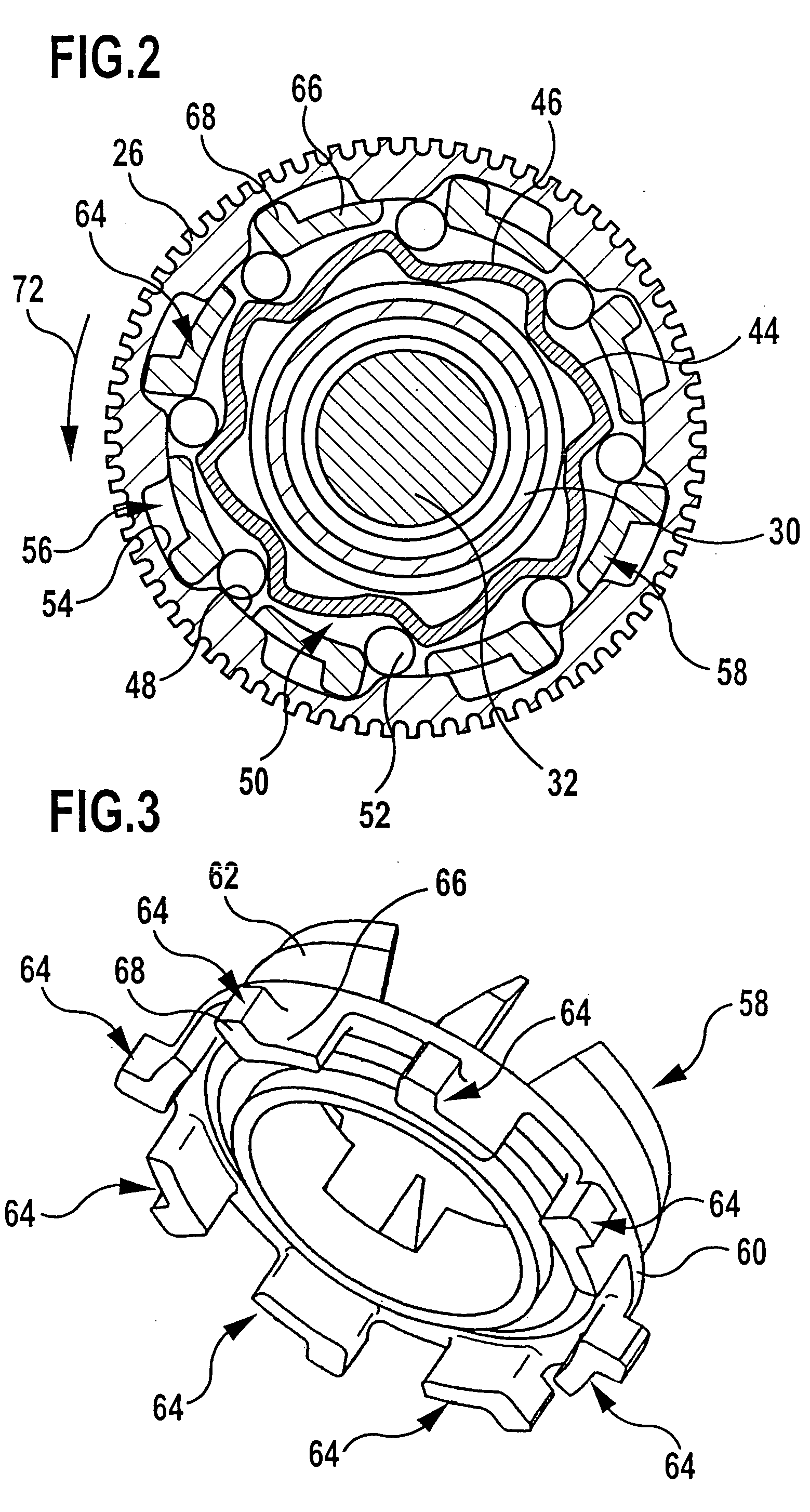
[0019] The intermediate part preferably forms an intermediate flange and the at least one overload element is preferably secured to the intermediate flange in the form of an axially protruding projection. This facilitates a configuration of the overload coupling in a constructionally simple manner such that the drive element and the driven element are arranged in a radial direction so as to be offset relative to one another and to form an annular space between them, into which the at least one overload element dips in that this is secured to the intermediate flange of the intermediate part in the form of an axially protruding projection. The intermediate part may, in this case, be positioned in axial direction to as to be offset in relation to the drive element and / or the driven element.
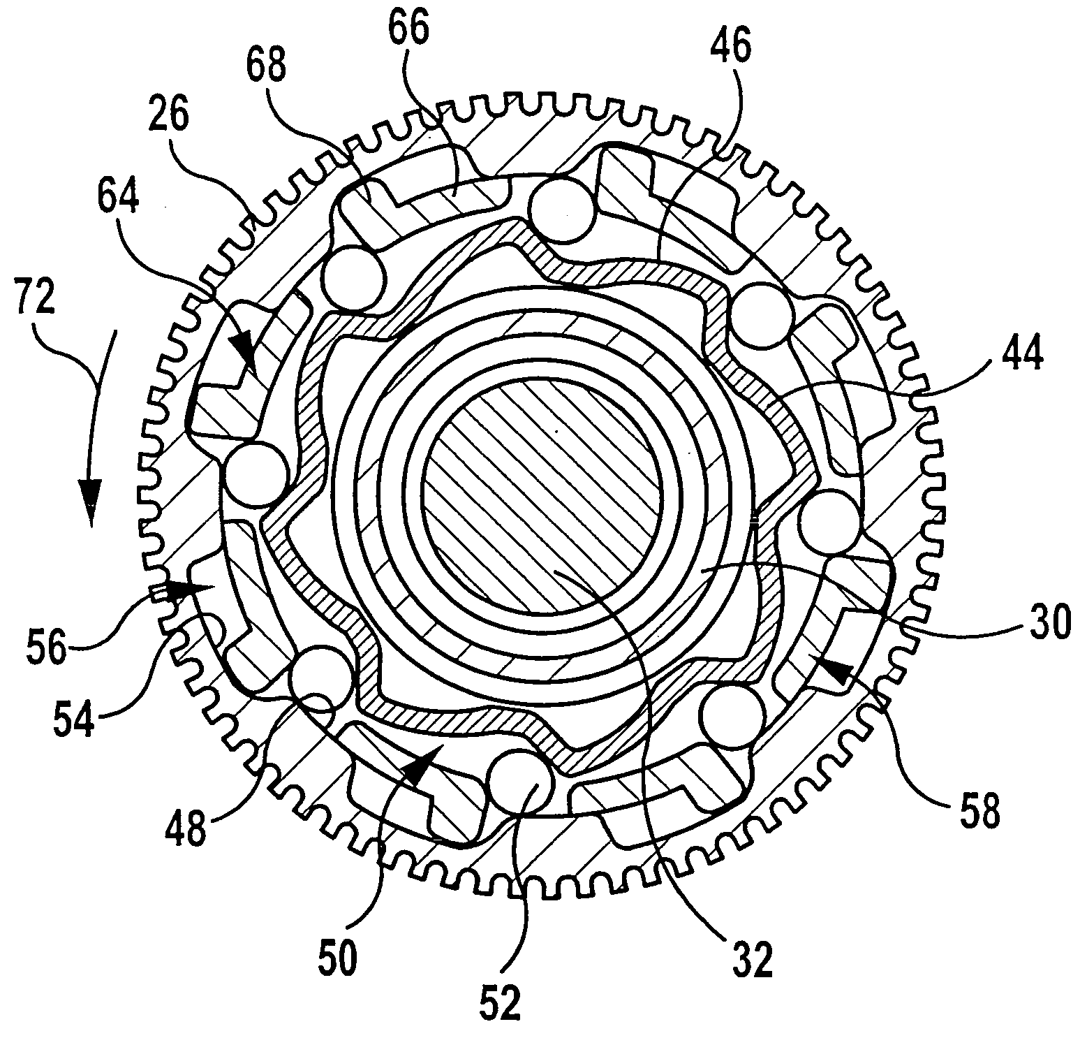
[0020] The driven element is preferably of a star-shaped configuration and has a plurality of stop surfaces which are aligned at an angle to the direction of rotation of the coupling element and on each of which a coupling element abuts in the coupling position. In this respect, it has proven to be particularly favorable to design the driven element with a shell surface which is configured essentially in the shape of saw teeth and on which several coupling elements abut in their coupling position, wherein the coupling elements can be positioned at a distance in relation to the driven element when an overload occurs by transferring into their alternative position so that the coupling elements can be freely rotated relative to the driven element and, as a result, a transfer of torque is prevented.
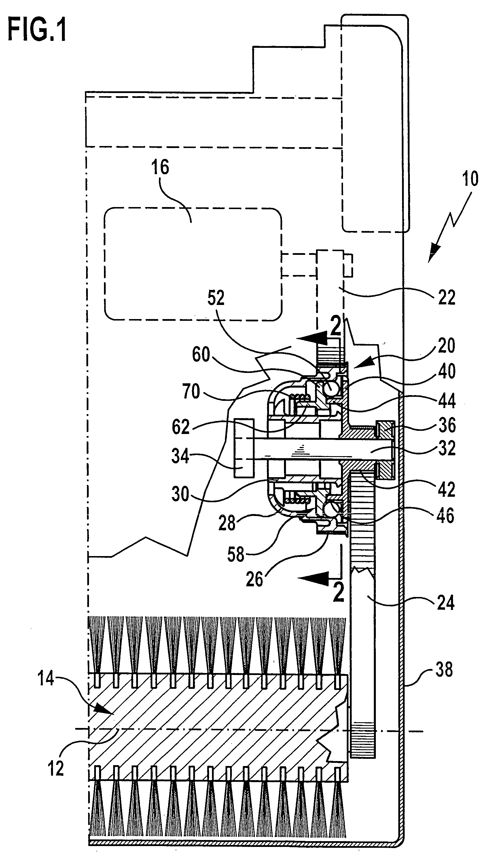
[0025] The floor cleaning device, for which the cleaning head according to the invention is provided, may be designed as a brush vacuum cleaner, with the aid of which a floor surface to be cleaned can be brushed and vacuumed at the same time. In this respect, it is of particular advantage when the drive motor drives not only a suction fan of the floor cleaning device but also its brush roller. The brush roller is driven so as to execute a rotational movement about a brush axis of rotation. If the brush roller is blocked or obstructed, the use of the overload coupling enables the drive motor to continue to be driven uninterrupted and without any motor overload occurring. The operation of the suction fan is, consequently, not influenced by any obstruction or blocking of the brush roller.

Problems solved by technology

Such an interruption occurs, in particular, when the rotation of the brush roller is blocked.
Torque can be transferred between two machine elements with their help, wherein this transfer is, however, interrupted when an overload occurs, i.e., when a maximum limiting value of the torque is exceeded.

Method used


Image

  • Cleaning head for floor cleaning device
  • Cleaning head for floor cleaning device
  • Cleaning head for floor cleaning device

Examples


Embodiment Construction

[0032] In FIG. 1, a cleaning head designated altogether with the reference numeral 10 is illustrated in a schematic manner; the cleaning head can be moved along a floor surface for the purpose of cleaning the floor surface, wherein the floor surface is brushed and vacuumed at the same time. For this purpose, the cleaning head comprises a brush roller 14 which is mounted so as to be rotatable about a brush axis 12 and can be caused to rotate by means of an electric motor 16. In addition, the cleaning head has, in a customary manner and not, therefore, illustrated in the drawings, a suction nozzle which is in flow communication with a suction unit which is known to the person skilled in the art and, therefore, likewise not illustrated so that the floor surface to be cleaned can be vacuumed by means of the cleaning head 10. The suction unit can have in the usual manner a suction fan which is, like the brush roller 12, caused to rotate by the electric motor 16.

[0033] The coupling of th...


PUM


Abstract

The invention relates to an overload coupling for the limited transfer of torque, in particular, for a floor cleaning device comprising a drive element and a driven element which are arranged concentrically to one another, thereby forming an intermediate space, wherein the intermediate space accommodates at least one coupling element which transfers torque and can be moved from the intermediate space into an alternative space contrary to the action of an elastic restoring force when an overload occurs. In order to design the overload coupling in a manner which is constructionally simpler and can be produced more inexpensively, it is suggested in accordance with the invention that the overload coupling have an overload element which is spring-loaded in the direction of rotation of the coupling element and releases the alternative space for the coupling element when the overload occurs. In addition, the invention relates to a cleaning head for a floor cleaning device with such an overload coupling.

Description

[0001] This application is a continuation of International application number PCT / EP2003 / 013532 filed on Dec. 2, 2003. [0002] The present disclosure relates to the subject matter disclosed in International application number PCT / EP2003 / 013532 of Dec. 2, 2003 and German application number 103 18 820.7 of Apr. 16, 2003, which are incorporated herein by reference in their entirety and for all purposes.BACKGROUND OF THE INVENTION [0003] The invention relates to a cleaning head for a floor cleaning device with a rotatable brush roller which is coupled to a drive motor via an overload coupling, wherein the overload coupling transfers only a limited torque. [0004] Cleaning heads of this type are used for floor cleaning devices, with the aid of which a floor surface to be cleaned can be cleaned, for example, can be brushed and vacuumed. The cleaning head comprises a rotatable brush roller which can be driven by a drive motor. An overload coupling is connected between the brush roller and th...

Claims


Application Information

Patent Timeline
IPC IPC(8): F16D7/06F16D7/10
CPCF16D7/10
Inventor HAEUSSERMANN, ULIJEUTTER, ROLAND
Owner ALFRED KARCHER GMBH & CO KG
Why Eureka
Try Eureka