Sensor system for monitoring surroundings on a mechanical component, and method for actuating and evaluating the sensor system

a sensor system and mechanical component technology, applied in mechanical devices, manufacturing tools, instruments, etc., can solve problems such as inability to integrate sensors, and inability to monitor surroundings without interruption

Active Publication Date: 2013-12-26
ROBERT BOSCH GMBH
View PDF4 Cites 14 Cited by
  • Summary
  • Abstract
  • Description
  • Claims
  • Application Information

AI Technical Summary

Benefits of technology

[0009]The present invention is based on the object of embodying a sensor system, attachable in simple fashion to a wide variety of components or surfaces of machines or machine parts, that at the same time enables compliance with safety standards that require mutually independent safety channels with a diagnostic function. The underlying idea of the invention is to embody sensor elements with a layered structure of flexible electrically conductive and electrically insulating plies, electrically conductive potential surfaces of one ply being disposed, laterally spaced apart via insulating plies located therebetween, in such a way that electric field lines form between the conductive potential surfaces and change measurably upon proximity and / or contact of a body or an object, the layered structure of a sensor element having at least two measuring elements operating separately from one another. The flexible layered structure makes possible simple adaptation and attachment of the sensor element and sensor system onto moving components of machines or complexly shaped surfaces of the machines, and the provision of at least two measuring elements for each sensor element, operating separately from one another, simultaneously allows safety standards to be met.
[0014]A particularly compact and simple configuration of the sensor elements is moreover made possible when the measuring elements are disposed together on at least one layer, and are physically separated from one another.
[0015]The invention also encompasses a method for applying control to and evaluating a sensor system according to the present invention. Provision is made in this context that when multiple sensor elements are present, at least one electronic evaluation device having means be provided, which device cyclically addresses the sensor elements and checks whether a significant change in capacitance with respect to a reference value has taken place in the context of at least one sensor element; and that the means address the at least two measuring elements of a sensor element in chronologically successive fashion. Such a method operates particularly reliably and dependably, since mutual influencing of the measured values of the two measuring elements of a sensor element is avoided.
[0016]Particularly fast and thus reliable sensing of impending collisions is enabled if a measuring element of a first sensor element and another measuring element of another sensor element are addressed at the same point in time by the means.
[0017]The design outlay and the outlay necessary for wiring the measuring elements can be reduced if the sequence of the sensor elements is used to address linearly concatenated sensor elements, by the fact that the data are forwarded along the chain to the means via multiple sensor elements.
[0018]Also particularly preferred is a method in which, in a further cycle, each sensor element is subjected to a self-diagnosis, the sensor elements being acted upon by test voltages or by a characteristic signal pattern. Such a method makes it possible in particular to reliably detect damage to the sensor elements, thus enabling particularly reliable operation of a sensor system.

Problems solved by technology

If the hazardous machine part has a surface of relatively complex shape or a complex trajectory, on the one hand uninterrupted sensor-based surroundings monitoring is often possible only with a great deal of outlay or in some cases not at all.
For example, optical sensing can be impeded by shadowing at edges and undercuts of the machine surface, or integration of sensors can also be impossible for lack of installation space.
Attachment of such an assemblage to different industrial robots is, however, often laborious.

Method used


Image

  • Sensor system for monitoring surroundings on a mechanical component, and method for actuating and evaluating the sensor system
  • Sensor system for monitoring surroundings on a mechanical component, and method for actuating and evaluating the sensor system
  • Sensor system for monitoring surroundings on a mechanical component, and method for actuating and evaluating the sensor system

Examples


Embodiment Construction

[0027]Identical components and components having the same function are labeled in the Figures with the same reference numbers.

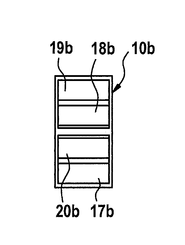
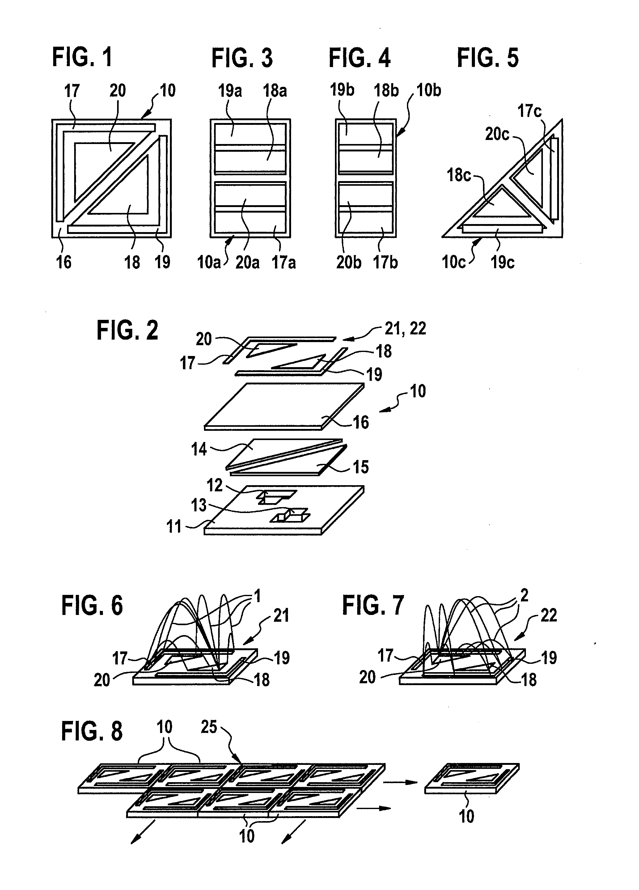
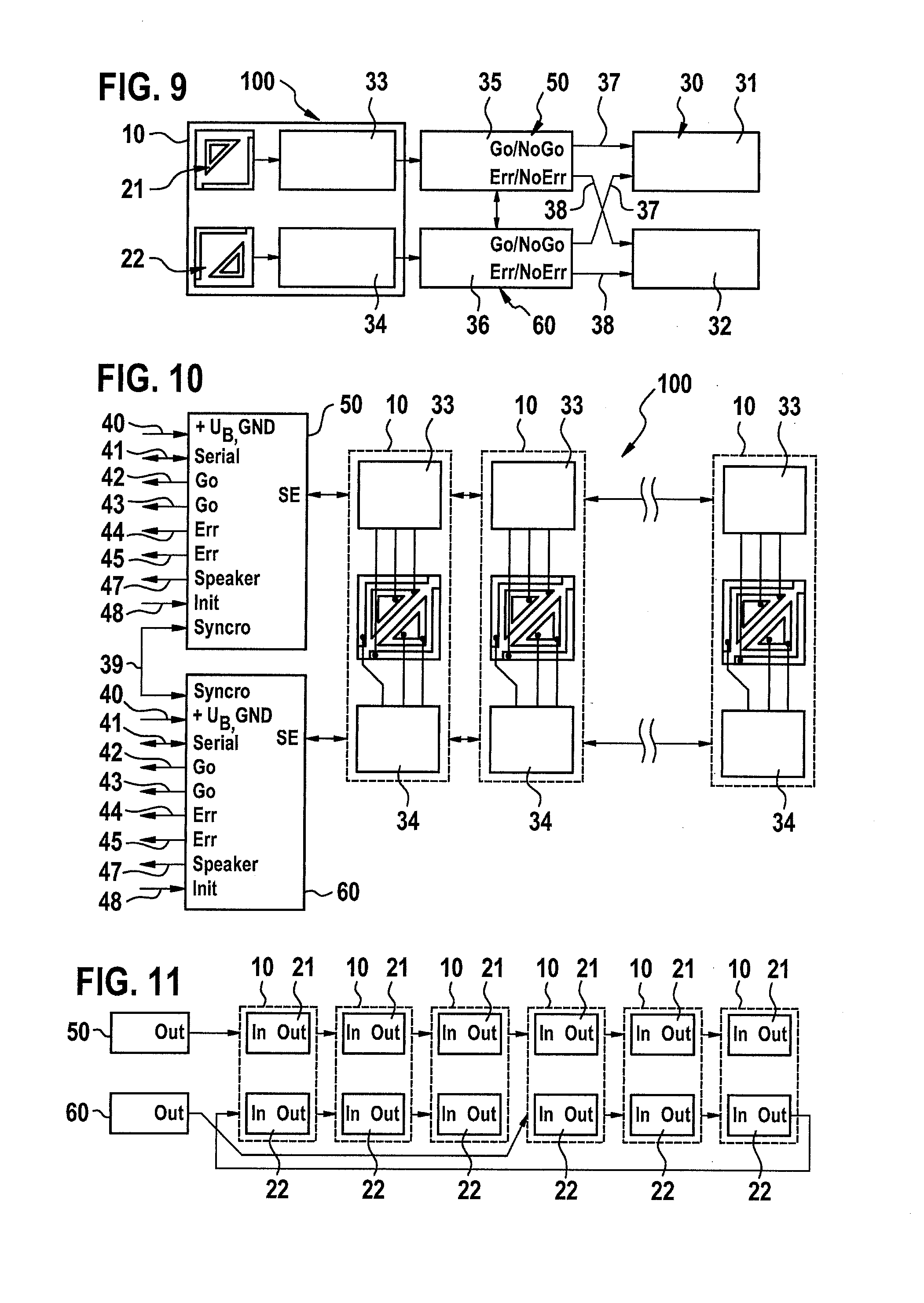
[0028]FIGS. 1 and 2 depict a sensor element 10 as a component of a sensor system 100 to be explained in further detail later. Sensor system 100 or sensor element 10 serves to monitor surroundings on a mechanical component, for example on a moving robot arm of an industrial robot or the like.

[0029]As is evident in particular from FIG. 2, sensor element 10 has a layered structure made up of multiple interconnected flexible layers. This layered structure contains, by way of example and therefore not in limiting fashion, a base layer 11, made for example of sponge rubber or rubber, having a thickness of, for example, 5 mm. Embodied within base layer 11 are two cutouts 12, 13 for the reception of an electronic system not depicted in FIGS. 1 and 2, or of electronic components. The underside of base layer 11 is disposed in abutment against, for example, the mechanic...


PUM


Abstract

A sensor system for monitoring surroundings on a mechanical component, includes at least one capacitive sensor element that is attachable to the surface of machines or machine parts, the at least one sensor element being constructed from a layered structure of flexible electrically conductive and electrically insulating plies, electrically conductive potential surfaces of one ply being disposed, laterally spaced apart via insulating plies located therebetween, in such a way that electric field lines form between the conductive potential surfaces and change measurably upon proximity and / or contact of a body or an object. The layered structure of a sensor element has at least two measuring elements operating separately from one another.

Description

BACKGROUND OF THE INVENTION[0001]1. Field of the Invention[0002]The present invention relates to a sensor system for monitoring surroundings on a mechanical component, and further relates to a method for applying control to, and for evaluating, a sensor system according to the present invention.[0003]2. Description of the Related Art[0004]Published German patent application document DE 10 2009 029 021 A1 (which is not considered a prior art) discloses a sensor system, which is attachable to surfaces of machines or machine parts, and which has at least one sensor element made up of a layered structure of flexible electrically conductive and electrically insulating plies. The proximity and / or contact of a body or an object can be measured using such a sensor system, for example in order to stop the operation of an assembly robot having a sensor system.[0005]It is furthermore known per se that for automatic proximity detection and / or collision detection, monitoring of the surroundings ...

Claims


Application Information

Patent Timeline
Patent Type & Authority Applications(United States)
IPC IPC(8): G01R27/26
CPCG01R27/2605B25J13/086B25J19/06G01D5/24G01L1/146F16P3/148G06F3/0445
Inventor FRANGEN, JOACHIM
Owner ROBERT BOSCH GMBH
Why Eureka
Try Eureka