Current protection for electrode-based monitoring systems

Active Publication Date: 2013-12-26
KONINKLIJKE PHILIPS ELECTRONICS NV
View PDF6 Cites 9 Cited by
  • Summary
  • Abstract
  • Description
  • Claims
  • Application Information

AI Technical Summary

Benefits of technology

[0010]It is an object of the present invention to provide a more effect

Problems solved by technology

Lower frequencies could cause twitching and cramps, which would be a serious problem.
However, these known implementations do not consider the issue of RF currents which are carried by a separate shield.
Especially, in ECG applications with shielded lead sets which are exposed to electrocautery RF energy, the problem arises that a current path is provided through the cable capacitance (inner conductor to shield).
Thus, when all shields are connected together, a high current may flow through the series connection of these cable capacities, thus causing skin burnings at the electrode sites at the patient.
However, a big disadvantage is that for a monitoring of respiration signals, which imply a low-impedance path to the patient, the ECG lead sets with built-in protection elements have to be replaced by such without protection elements.
This is time-consuming and circumstantial, so it is highly desirable to avoid this procedure.
However, the method of using inductors for separatin

Method used


Image

  • Current protection for electrode-based monitoring systems
  • Current protection for electrode-based monitoring systems

Examples


Example

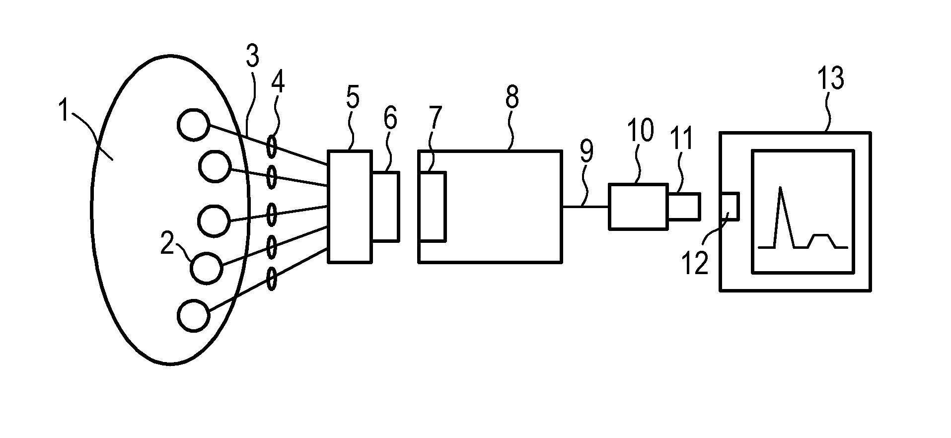
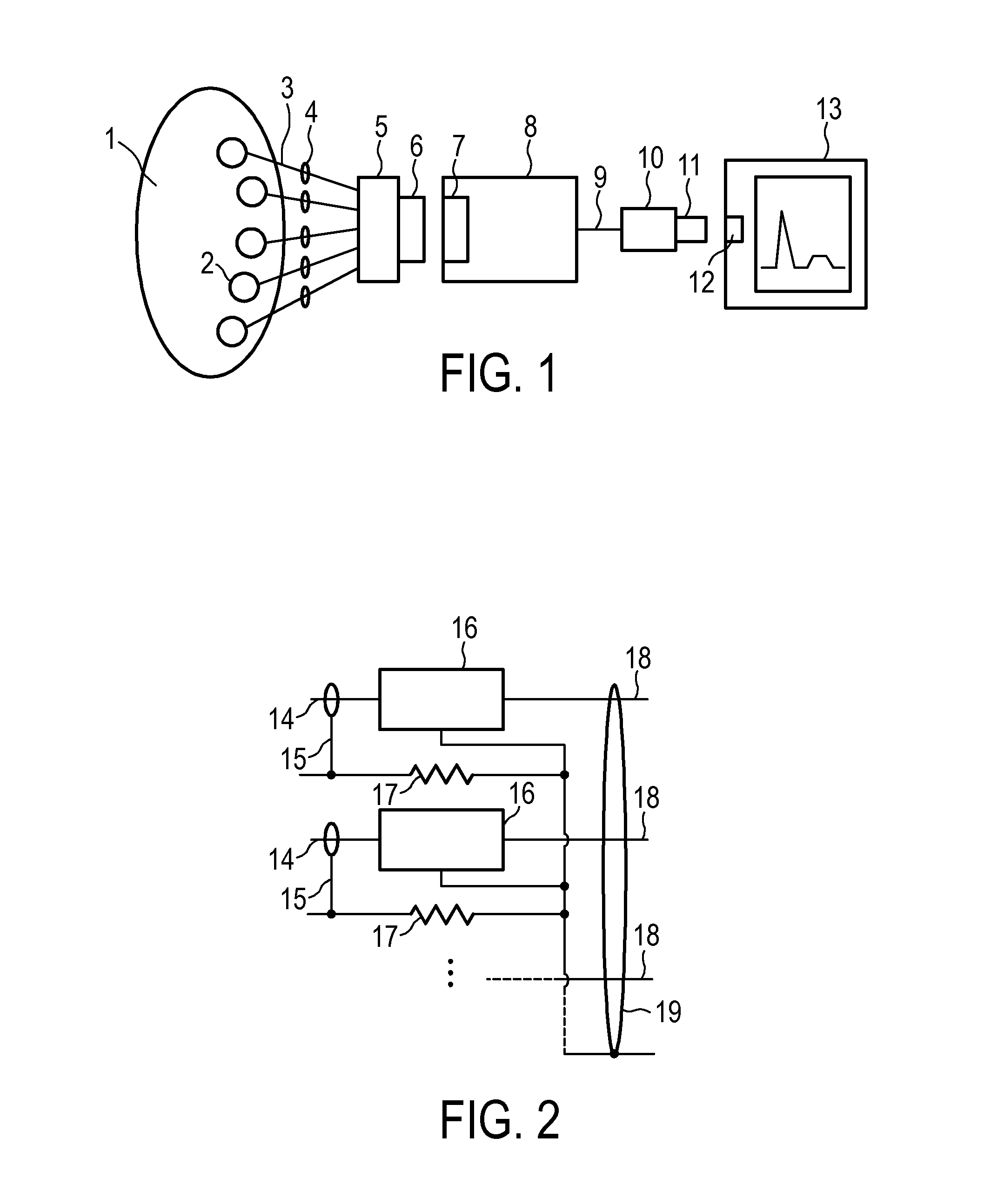
[0022]In the following embodiment, an enhanced protection against excessive shield currents for patient monitoring devices, such as ECG devices, is described.

[0023]According to the embodiment, shield cable currents can be reduced dramatically when the shields of the lead cable are separated by connecting at least one series resistance into or to the shield conductor(s). These resistors may for example be provided in an ECG trunk cable to allow the usage of uniform lead cables for all applications.

[0024]Usually, the coupling capacitance of the lead cable to 50 / 60 Hz sources is in the range of some picofarads (pF). Under extreme circumstances, it could increase to about 100 pF.

[0025]This results in a coupling impedance which will be in the range of some 1000 MΩ, under extreme circumstances it could decrease to about 30 MΩ. Compared with these values, a resistance of e.g. 10 kΩ will decrease a common mode signal of 100 V and 30 MΩ source impedance—which is an absolute worst case—to onl...


PUM


Abstract

When applying shielded ECG leads to a patient, during the presence of strong RF signals such as electrocautery, high currents may flow through the cable capacitance to the shield and from there back to the patient via another cable capacitance and electrode, thus causing skin burnings. Such high currents can be reduced dramatically when the shields of the lead cable are separated by means of connecting series resistances into the shield conductors. Implementing these resistors into a ECG trunk cable allows the usage of uniform lead cables for all applications.

Description

FIELD OF THE INVENTION[0001]The present invention relates to an apparatus for protecting patients connected to electrode-based monitoring systems, such as electrocardiogram (ECG) devices, against excessive current which, for example, may be caused by electrocautery applications.BACKGROUND OF THE INVENTION[0002]During monitoring of ECG signals, surgeons often use electrocautery devices. Electrocautery is a surgical technique which involves introducing high frequency current to a specific area of the body in order to remove unwanted tissue, seal off blood vessels, or to create a surgical incision. The instrument used to perform electrocautery is also known as an electrocautery. An electrocautery uses a high frequency, usually upwards of 100 kHz, to ensure that the patient's nerves and muscles are not stimulated. Lower frequencies could cause twitching and cramps, which would be a serious problem. Depending on the voltage used, the electrocautery can have varying effects on the patient...

Claims


Application Information

Patent Timeline
IPC IPC(8): A61B5/0424A61B5/276A61B5/308
CPCA61B5/04282A61B2560/045A61B5/0424A61B2562/227A61B2562/222A61B5/301A61B5/30A61B5/276
Inventor ELSCHENBROICH, RAINER WILLI
Owner KONINKLIJKE PHILIPS ELECTRONICS NV
Why Eureka
Try Eureka