Fire rated door

a fire-rated door and door body technology, applied in the field of door manufacturing, can solve the problems of reducing the strength of the door, requiring the internal mineral core, and not being able to fully automate the manufacturing process,

Active Publication Date: 2014-01-02
THE INTELLECTUAL GORILLA
View PDF21 Cites 27 Cited by
  • Summary
  • Abstract
  • Description
  • Claims
  • Application Information

AI Technical Summary

Benefits of technology

[0007]In addition, the present invention provides a method of manufacturing a fire rated door by providing a core, attaching a first decorative panel to a top of the core, and attaching a second decorative panel to a bottom of the core. The core is provided by providing a fire resistant center panel, attaching a first stile of an extruded fire resistant border to the first side of the fire resistant center panel, attaching a second stile of the extruded fire resistant border to the second side of the fire resistant center panel, attaching a first rail of the extruded fire resistant border to the first end of the fire resistant center panel and the first stile and the second stile of the extruded fire resistant border, and attaching a second rail of the extruded fire resistant border to the second end of the fire resistant center panel and the first stile and the second stile of the extruded fire resistant border. The fire resistant center panel has a bottom, a top, a first side, a second side, a first end and a second end. The fire resistant center panel is made of a first fire resistant material. The extruded fire resistant border is made of a second fire resistant material having a higher density than the first fire resistant material.

Problems solved by technology

But most of these prior art designs do not lend themselves well to fully automated manufacturing processes.
Moreover, the prior art fire rated doors are expensive and require the internal mineral core.
The internal core can be exposed in routed details and may reduce the strength of the door as a result of the reduced thickness of the door panels.
In addition, alignment of the panels during assembly can be troublesome and require additional finishing to square the door after assembly.

Method used


Image

  • Fire rated door
  • Fire rated door
  • Fire rated door

Examples


Embodiment Construction

[0038]While the making and using of various embodiments of the present invention are discussed in detail below, it should be appreciated that the present invention provides many applicable inventive concepts that can be embodied in a wide variety of specific contexts. The specific embodiments discussed herein are merely illustrative of specific ways to make and use the invention and do not delimit the scope of the invention. The discussion herein relates primarily to fire rated doors, but it will be understood that the concepts of the present invention are applicable to any type of door.

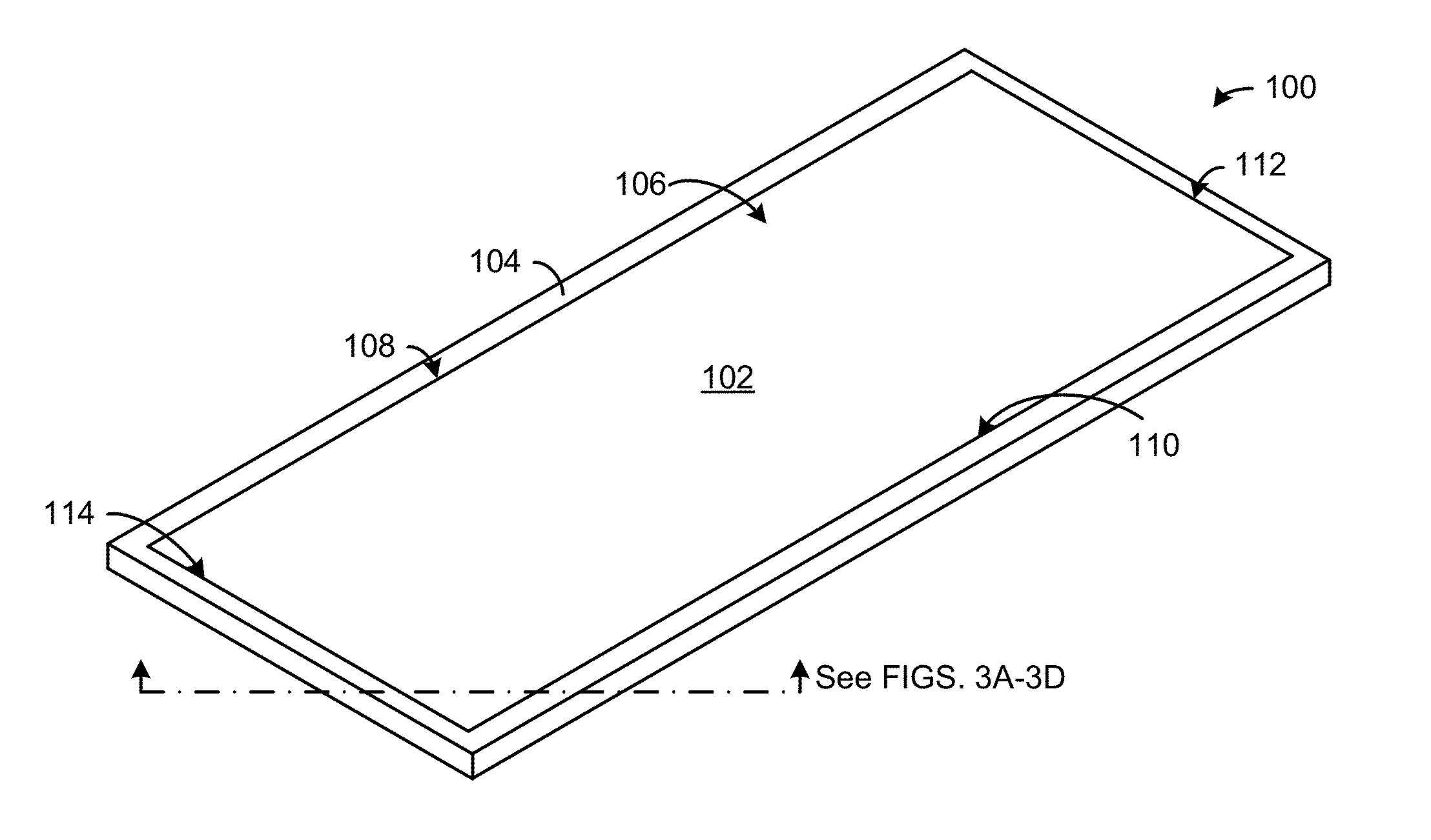
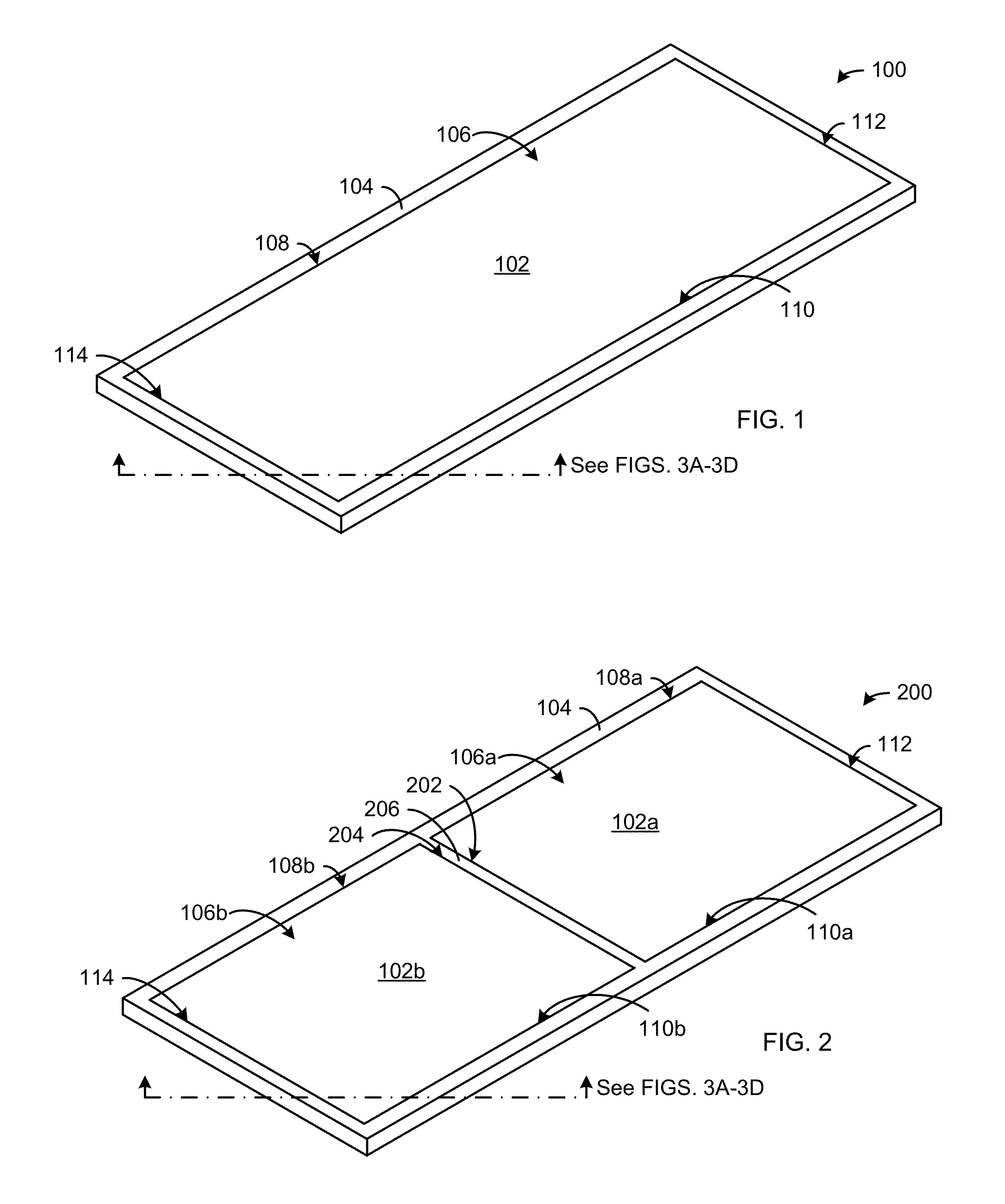
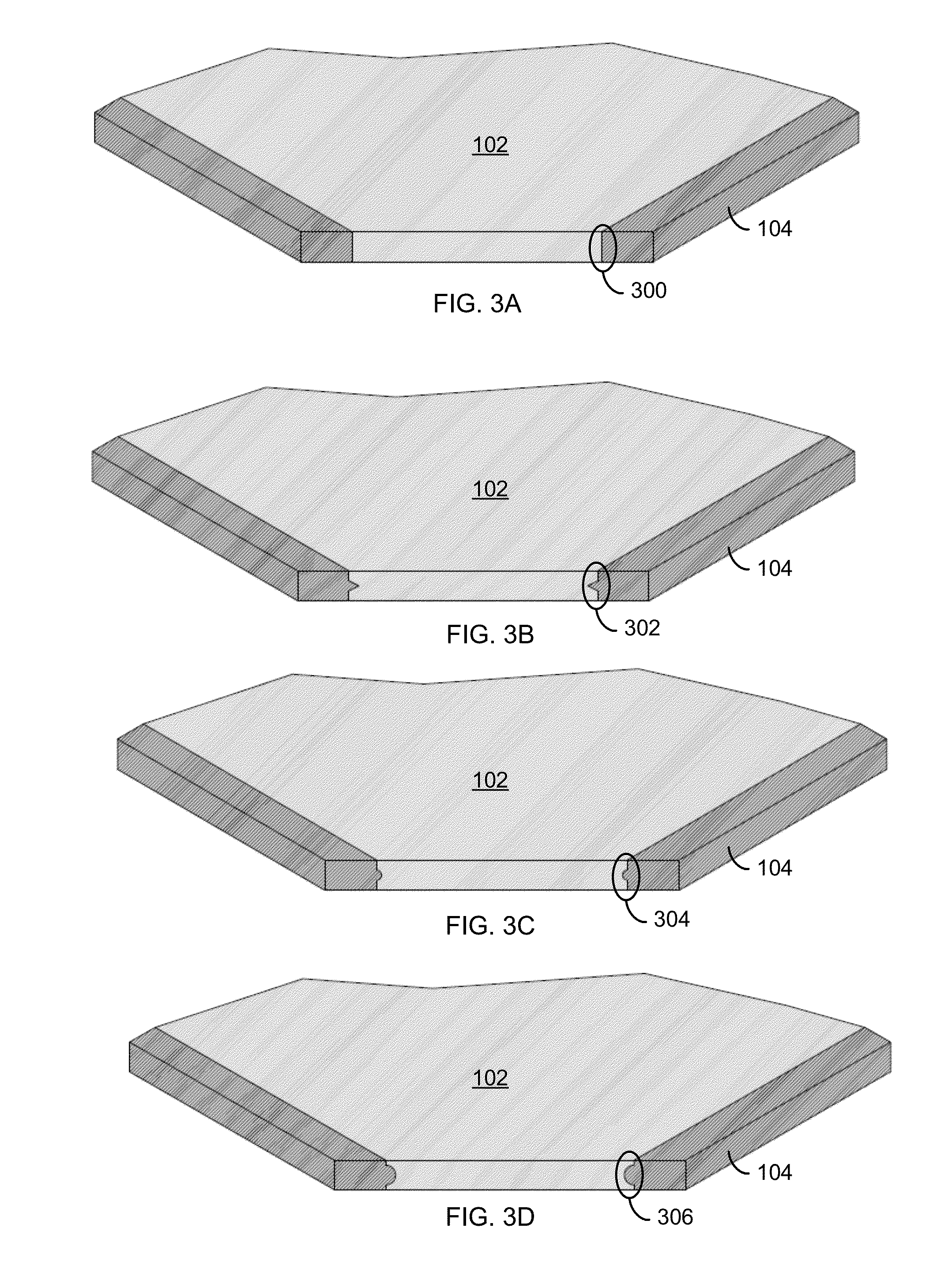
[0039]The door core of the present invention provides the fire resistant capabilities necessary to receive the necessary certification. The length and width of the fire core will match the length and width specifications of the final door product. The dimensions of the fire core will typically be in widths of three feet and four feet and having a length ranging from seven feet to ten feet. The thickn...


PUM

PropertyMeasurementUnit
lengthaaaaaaaaaa
lengthaaaaaaaaaa
widthsaaaaaaaaaa

Abstract

A fire rated door includes a core, a first decorative panel and a second decorative panel. The core includes: (a) a fire resistant center panel having a bottom, a top, a first side, a second side, a first end and a second end, wherein the fire resistant center panel is made of a first fire resistant material, and (b) an extruded fire resistant border attached to the first side, the second side, the first end and the second end of the fire resistant center panel, wherein the extruded fire resistant border is made of a second fire resistant material having a higher density than the first fire resistant material. The first decorative panel is attached to the top of the fire resistant center panel and the extruded fire resistant border. The second decorative panel is attached to the bottom of the fire resistant center panel and the extruded fire resistant border.

Description

PRIORITY CLAIM AND CROSS-REFERENCE TO RELATED APPLICATIONS[0001]This patent application is related to U.S. patent application Ser. No. ______ filed on Jun. 29, 2012 and entitled “Fire Rated Door Core”, which is hereby incorporated by reference in its entirety.FIELD OF THE INVENTION[0002]The present invention relates generally to the field of door manufacturing and, more particularly, to a fire rated door.BACKGROUND OF THE INVENTION[0003]Many methods and techniques for manufacturing fire rated doors have been developed over time. But most of these prior art designs do not lend themselves well to fully automated manufacturing processes. Moreover, the prior art fire rated doors are expensive and require the internal mineral core. The internal core can be exposed in routed details and may reduce the strength of the door as a result of the reduced thickness of the door panels. In addition, alignment of the panels during assembly can be troublesome and require additional finishing to squa...

Claims


Application Information

Patent Timeline
Patent Type & Authority Applications(United States)
IPC IPC(8): E06B5/16B21K23/00E04B1/94E04C2/32E04B1/92B29C48/07
CPCE06B2003/7036E06B2003/7038E06B2003/7042E06B2003/7059E06B3/7017E06B5/16E06B2003/7019Y10T29/49826B29C48/001B29C48/07Y10T29/49629E06B2003/7051E06B2003/709E06B3/822E06B5/164E06B5/20B29C39/10B29C65/565B29K2105/0026B29K2105/16B29K2995/0015B29L2031/724E06B5/161
Inventor DANIELS, EVAN R.NEWTON, JONATHAN
Owner THE INTELLECTUAL GORILLA
Why Eureka
Try Eureka