End mill for cutting of high-hardness materials

a cutting and high-hardness technology, applied in the direction of milling equipment, metal working equipment, metal-working apparatus, etc., can solve the problems of poor cutting speed, less machinability, and more rapid abrasion, and achieve enhanced chip removal, high cutting rate, and rigid edge rigidity

Active Publication Date: 2014-01-02
HITACHI TOOL ENG LTD
View PDF38 Cites 20 Cited by
  • Summary
  • Abstract
  • Description
  • Claims
  • Application Information

AI Technical Summary

Benefits of technology

[0033]In the end mill of the present invention, when seen from a direction parallel to the tool axis, the arc-shaped cutting edge and the rim at the rearward side of the rotation at the flank of the arc-shaped cutting edge form curves with radii of curvatures, and the radius of curvature of the arc-shaped cutting edge is smaller than the radius of curvature of the rim at the rearward side of the rotation at the flank of the arc-shaped cutting edge. Therefore, chip removability is enhanced. Further, the width of the flank of the arc-shaped cutting edge becomes narrower as it approaches the center of the tool axis, and the flank becomes wider at the outer periphery. Therefore, the rigidity of the edge on the outer periphery increases, allowing higher cutting rate and cutting at higher feed rate. Thus, the enhancement of cutting efficiency is enabled.
[0034]In the present invention, it is preferable that, when seen from a direction parallel to the tool axis, the radius of curvature of the arc-shaped cutting edge is larger than the tool radius. This allows the flank at the outer periphery to become wider, which allows the width of the flank at the outer-most periphery of the tool, i.e., the connective part of the arc-shaped cutting edge and the peripheral edge, where the cutting resistance is at its maximum, to be largest. Therefore, the rigidity of the connective part of the arc-shaped cutting edge and the peripheral edge is further enhanced, enabling stable cutting without fractures even during high-efficiency cutting.
[0035]In the present invention, it is preferable that the radius of curvature of the arc-shaped cutting edge is in the range of 0.3 times or above to 0.7 times or below the radius of curvature of the rim at the rearward side of the rotation at the flank of the arc-shaped cutting edge. This further allows chip removability to increase, enabling high-efficiency machining of 1.5 times or above, compared to conventional end mills, even in the roughing of molds with corners mad...

Problems solved by technology

However, in a ball end mill, because the cutting amount in the vicinity of the central part becomes large, cutting rate does not increase, leading to inferior machinability.
In addition, there is a disadvantage in that the chip pocket in the vicinity of the central part is small, and chip removal is poor.
In the high-efficiency roughing of such high...

Method used


Image

  • End mill for cutting of high-hardness materials
  • End mill for cutting of high-hardness materials
  • End mill for cutting of high-hardness materials

Examples


example

Example 1

[0117]To verify the advantages of the end mill of the present invention, a cutting test was performed by machining a pocket shape. For the cutting test, examples of the present invention and comparative examples were used. The specifications of each tool were as follows.

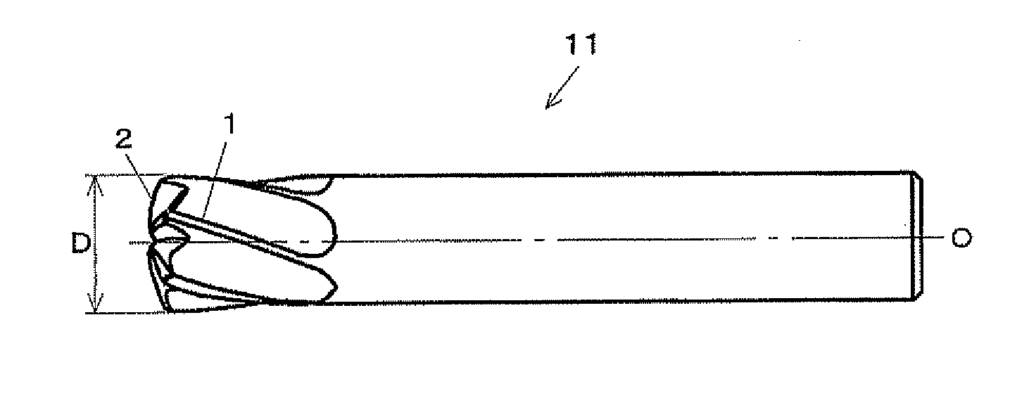
[0118]In Example 1, Present Invention Example 1 and Conventional Examples 2 and 3 were used. As common dimensions of the end mill form, the tool diameter D was 10 mm, the core diameter was 7.5 mm, the angle of torsion of the peripheral edge was 20 degrees, the number of cutting edges was 6, the coating was TiSiN-type and the base material was cemented carbide.

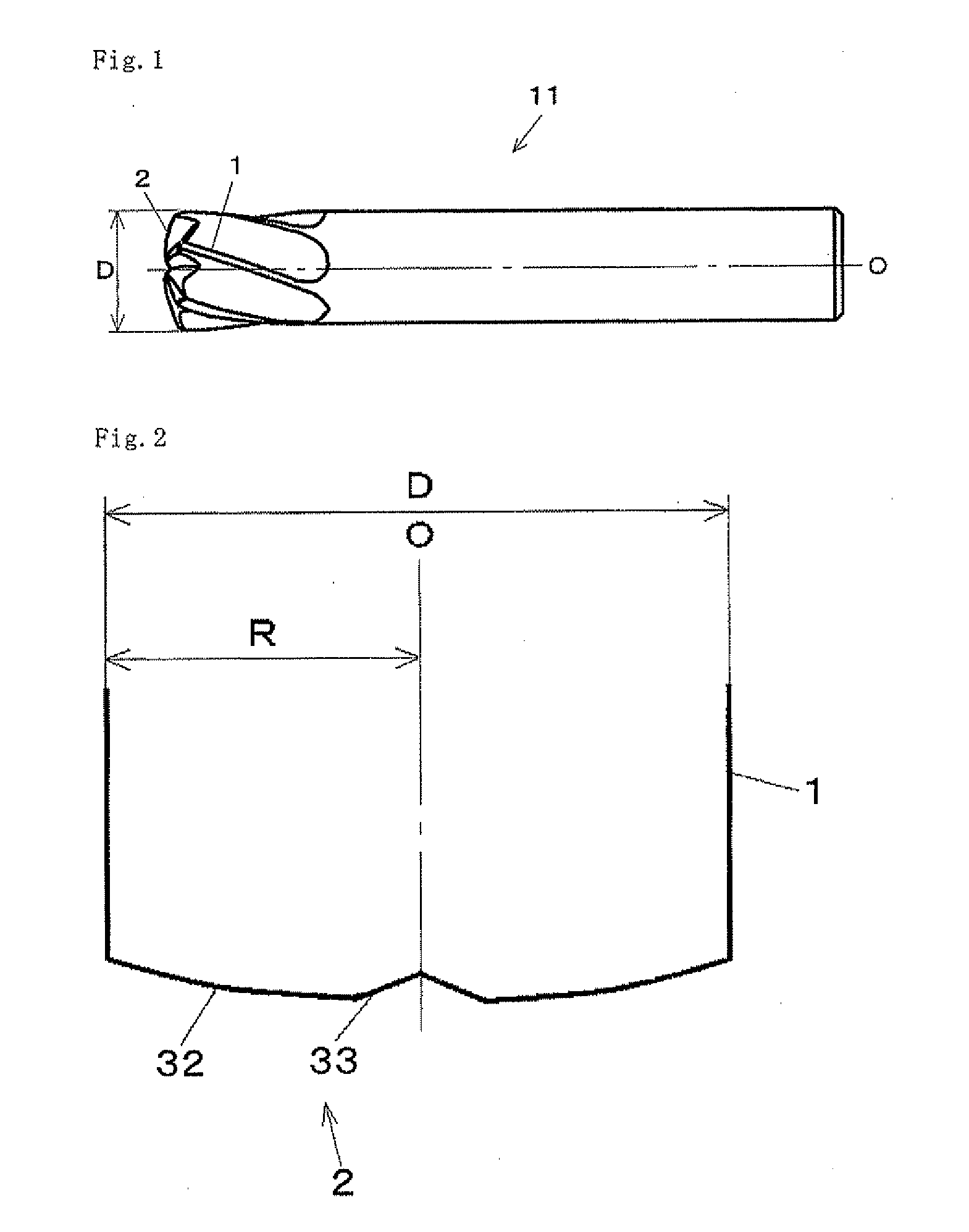
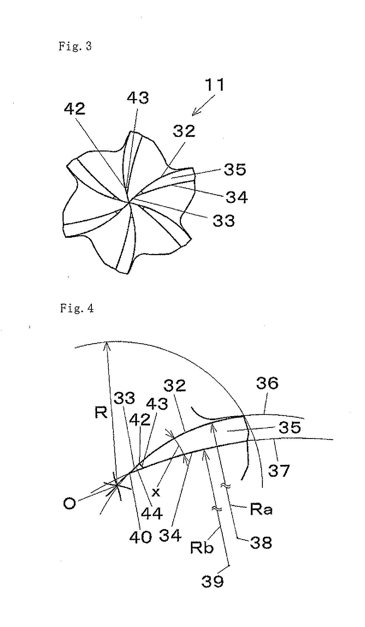
[0119]In Present Invention Example 1 and Conventional Examples 2 and 3, the radius of curvature of the rim at the rearward side of the rotation at the flank of the arc-shaped cutting edge was set at 13 mm, and end mills of varying radius of curvatures of the arc-shaped cutting edge were prepared.

[0120]For Present Invention Example 1, an end mill with th...

example 2

[0127]In Example 2, in order to confirm the relationship between the radius of curvature of the arc-shaped cutting edge and the radius of curvature of the rim at the rearward side of the rotation at the flank of the arc-shaped cutting edge, a cutting test was performed by cutting a pocket shape, as in Example 1.

[0128]In Example 2, Present Invention Examples 4 to 10 were used. As common dimensions of the end mill form, as with Present Invention Example 1 used in Example 1, the tool diameter D was 10 mm, the core diameter was 7.5 mm, the angle of torsion of the peripheral edge was 20 degrees, the number of cutting edges was 6, the radius of curvature of the rim at the rearward side of the rotation at the flank of the arc-shaped cutting edge was set at 2.6 times that of the tool radius, or 13 mm, the coating was TiSiN-type and the base material was cemented carbide, and an end mill wherein the bottom edge and the peripheral edge were connected was prepared.

[0129]For Present Invention E...

example 3

[0138]In Example 3, in order to confirm the relationship between the radius of curvature of the arc-shaped cutting edge and the tool radius, a cutting test was performed by cutting a pocket shape, as in Example 1.

[0139]In Example 3, Present Invention Examples 11 to 17 were used. As common dimensions of the end mill form, as in Present Invention Example 1 used in Example 1, an end mill with the bottom edge and the peripheral edge connected together, with a tool diameter D of 10 mm, a core diameter of 7.5 mm, an angle of torsion of the peripheral edge of 20 degrees, number of cutting edges of 6, a radius of curvature of the rim at the rearward side of the rotation at the flank of the arc-shaped cutting edge set at 2.6 times the tool radius, or 13 mm, a coating of TiSiN-type, and a base material of cemented carbide, was prepared.

[0140]For Present Invention Example 11, one with a radius of curvature of the arc-shaped cutting edge set at 5 mm, and the radius of curvature of the arc-shape...


PUM


Abstract

The present invention relates to an end mill, which comprises a bottom edge, which is composed of an arc-shaped cutting edge that is curved when seen from a direction perpendicular to the tool axis and a linear or curved medium-to-low inclination cutting edge, and a peripheral edge, wherein, when seen from a direction parallel to the tool axis, the arc-shaped cutting edge and a rim at the rearward side of the rotation at a flank of the arc-shaped cutting edge are curved with radii of curvatures, and the radius of curvature of the arc-shaped cutting edge is smaller than the radius of curvature of the rim at the rearward side of the rotation at the flank of the arc-shaped cutting edge.

Description

TECHNICAL FIELD[0001]The present invention relates to an end mill for cutting of high-hardness materials.BACKGROUND ART[0002]In recent years, there has been an increase in demand for shortening the delivery time of molds, and thus, a highly efficient process for preparing molds has been desired. For the high-efficiency roughing of molds, ball end mills and radius end mills are widely in use. However, in a ball end mill, because the cutting amount in the vicinity of the central part becomes large, cutting rate does not increase, leading to inferior machinability. In addition, there is a disadvantage in that the chip pocket in the vicinity of the central part is small, and chip removal is poor. Therefore, recently, radius end mills are used more often for the high-efficiency roughing of molds. By using a radius end mill, because the cutting amount at the outer periphery becomes larger, the chip pocket becomes wider. Thus, chip removability becomes good, and cutting is performed at hig...

Claims


Application Information

Patent Timeline
IPC IPC(8): B23C5/10
CPCB23C5/1009B23C5/10B23C2210/082B23C2210/084B23C2210/205B23C2210/54Y10T407/1948Y10T407/1964B23C5/16B23C2210/0435
Inventor HAN, GANGMAEDA, KATSUTOSHI
Owner HITACHI TOOL ENG LTD
Why Eureka
Try Eureka