Construction machine

a construction machine and construction technology, applied in the direction of machines/engines, electric control, speed sensing governors, etc., can solve the problem of easy blockage of filters, and achieve the effect of increasing the load of engines

Inactive Publication Date: 2014-01-09
NIHON KENKI CO LTD
View PDF21 Cites 12 Cited by
  • Summary
  • Abstract
  • Description
  • Claims
  • Application Information

AI Technical Summary

Benefits of technology

[0008]On the other hand, in the construction machine that is represented by the hydraulic excavator, it becomes a mainstream to perform automatic idle control with the aim of saving and reduction of a fuel consumption quantity or reduction of noises. This automatic idle control in advance operates a selection switch in a case where a hydraulic actuator in a working machine continues to stop over a predetermined time. Therefore, a rotational speed of an engine is lowered to an automatic idle rotational speed (that is, rotational speed for non-load operation). However, the rotational speed of the engine is maintained to a low rotational speed while performing the automatic idle control. Therefore, a temperature of the exhaust gas is lowered, and in the particulate matter removing unit in the exhaust gas purifying apparatus, the filter tends to be easily clogged by deposit of the particulate matter.
[0009]In view of the aforementioned problems in the conventional art, it is an object of the present invention to provide a construction machine in which at the time of executing a regeneration process for an exhaust gas purifying apparatus in a state of performing automatic idle control, a temperature of the exhaust gas can easily be increased to a temperature necessary for regenerating the exhaust gas purifying apparatus by increasing a rotational speed of an engine to a regeneration processing rotational speed higher than an automatic idle rotational speed.
[0012]With this arrangement, at a non-load operation of the engine (or at an operation where a load is small) in which all the hydraulic actuators stop, the rotational speed of the engine can be lowered to the automatic idle rotational speed to suppress wasteful consumption of fuel and achieve reduction of engine noises. In a case where the filter in the exhaust gas purifying apparatus is clogged by trapping, collecting and depositing the particulate matter at such automatic idle control, operating the regeneration apparatus enables a low-temperature regeneration process that increases a temperature of the exhaust gas. Moreover, since the rotational speed of the engine is increased to the regeneration processing rotational speed at this time, the processing operation of the regeneration apparatus can stably be performed thereby, and for example, the regeneration of the filter can smoothly be performed by burning off the particulate matter that is deposited in the filter in the particulate matter removing unit with the exhaust gas that has increased in temperature.
[0013]As a result, even when the temperature of the exhaust gas is lowered by a non-load operation or a light-load operation of the engine following the automatic idle control, the rotational speed of the engine is increased to the regeneration processing rotational speed, thus making it possible to easily increase the temperature of the exhaust gas to a temperature necessary for regenerating the exhaust gas purifying apparatus and execute the regeneration process to the exhaust gas purifying apparatus at a temperature as low as possible. As a result, the filter can be regenerated by burning off the particulate matter deposited in the filter of the particulate matter removing unit to stably execute the purifying process of the exhaust gas. Accordingly, reliability of the exhaust gas purifying apparatus can be improved.
[0018]With this arrangement, when the rotational speed of the engine is the rotational speed lower than the regeneration processing rotational speed, the engine can be stopped after performing the automatic idle control over a predetermined time. As a result, it is possible to prevent the regeneration process to the exhaust gas purifying apparatus by the regeneration apparatus from continuing to be executed in a low-rotational speed state of the engine (that is, a state of a rotational speed lower than the regeneration processing rotational speed).
[0020]With this arrangement, the regeneration apparatus that executes the regeneration process to the exhaust gas purifying apparatus can be constituted by the throttle valve provided in at least one of the intake side and the exhaust side of the engine. For example, when the filter in the exhaust gas purifying apparatus (particulate matter removing unit) is clogged, the throttle valve in the intake side, without performing the high-temperature regeneration by the post-injection, can execute the low-temperature regeneration process for increasing an exhaust gas temperature by throttling an intake air quantity in such a manner that an air-fuel ratio of air and fuel is closer to a rich side, for example. On the other hand, the throttle valve provided in the exhaust side of the engine can execute the low-temperature regeneration process for increasing the exhaust gas temperature as a result of increasing a load of the engine by throttling a flow of an exhaust gas.

Problems solved by technology

Therefore, a temperature of the exhaust gas is lowered, and in the particulate matter removing unit in the exhaust gas purifying apparatus, the filter tends to be easily clogged by deposit of the particulate matter.

Method used


Image

  • Construction machine
  • Construction machine
  • Construction machine

Examples


first embodiment

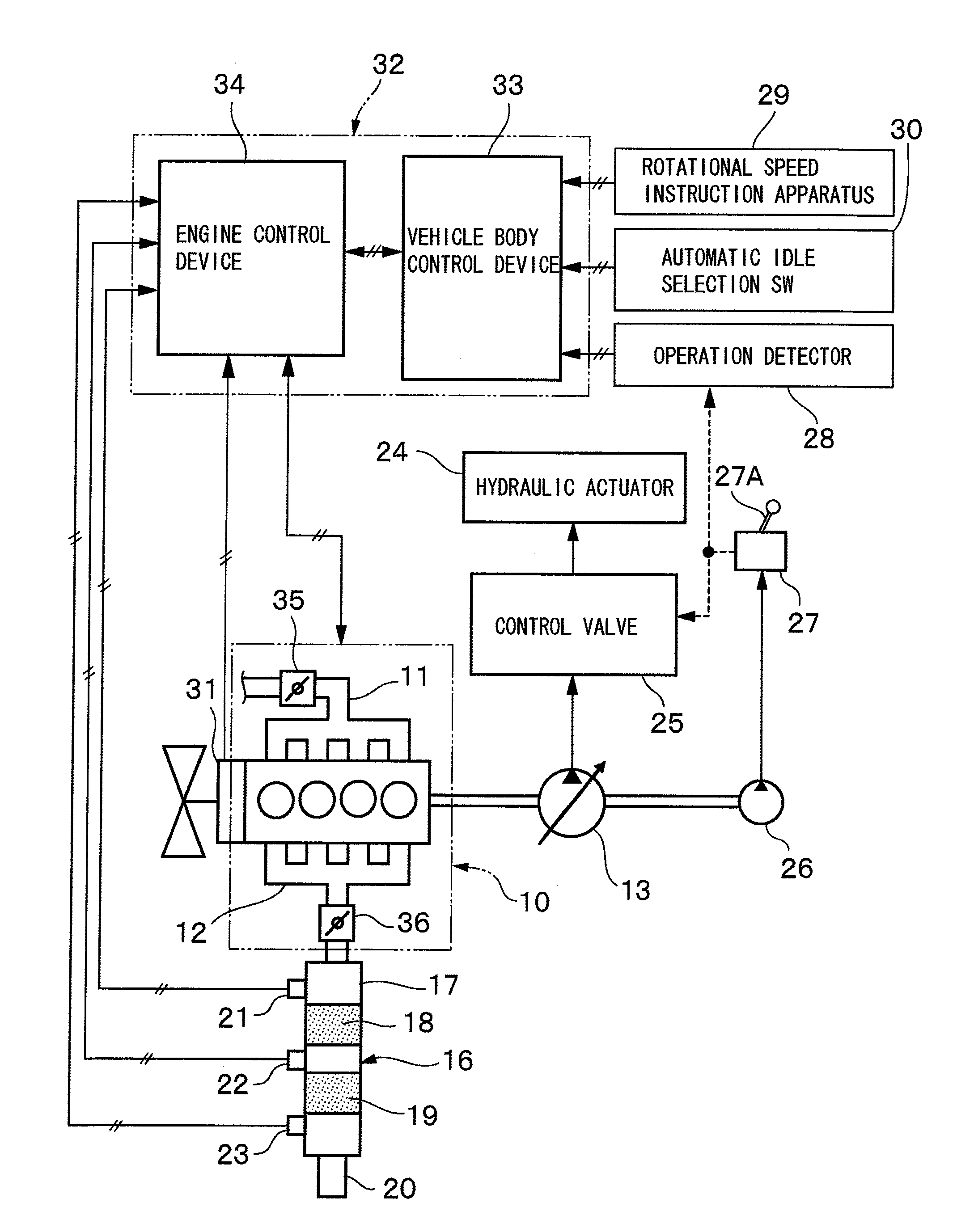
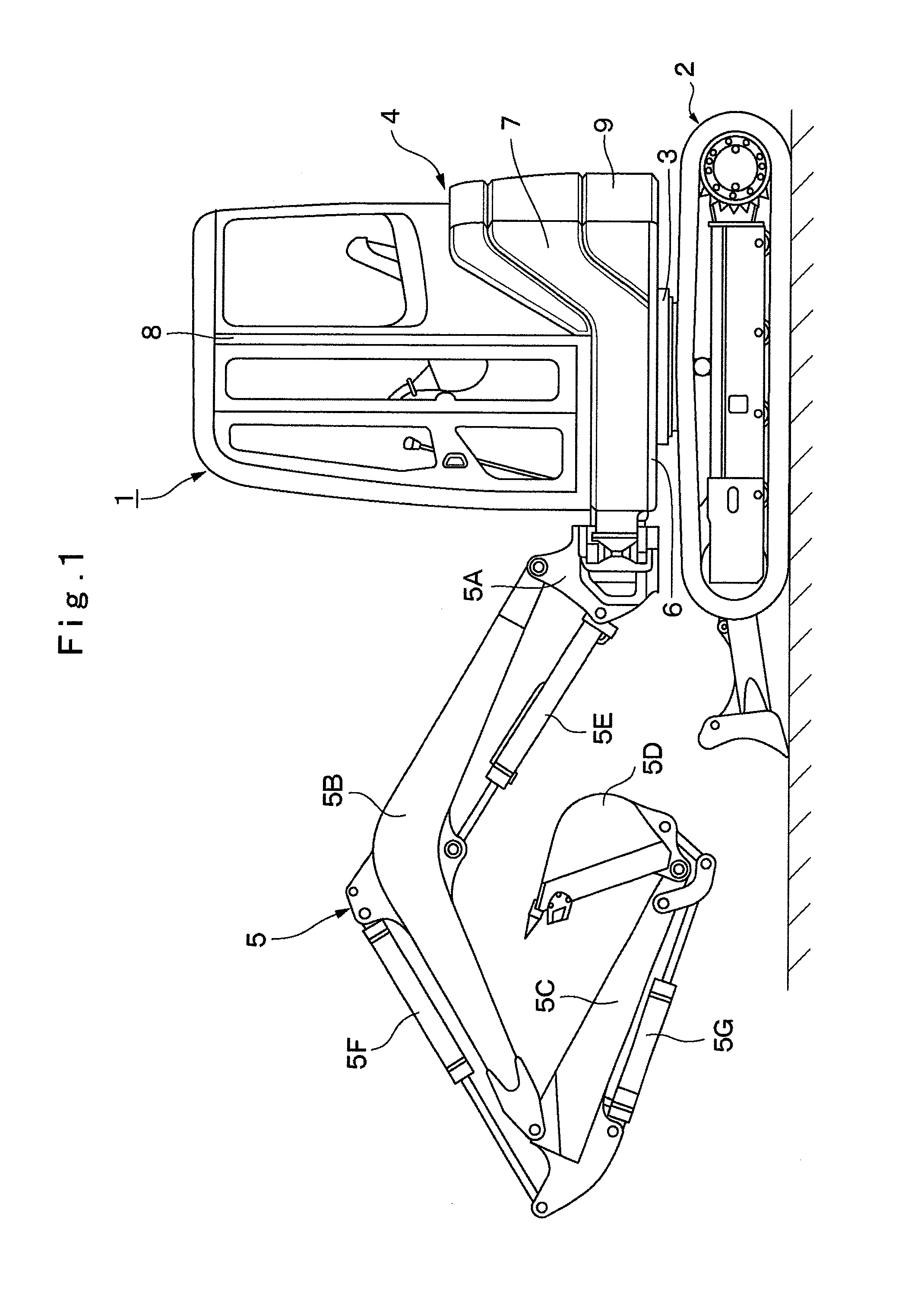
[0031]Here, FIG. 1 to FIG. 6 show a hydraulic excavator provided with an exhaust gas purifying apparatus in the present invention.

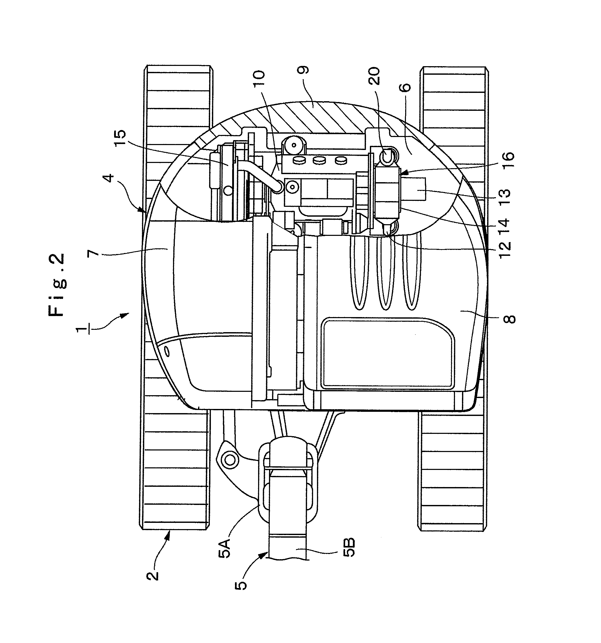
[0032]In the figure, designated at 1 is a small-sized hydraulic excavator that is used for an excavating operation of earth and sand, and the like. The hydraulic excavator 1 is largely constituted by an automotive crawler type lower traveling structure 2, an upper revolving structure 4 that is mounted on the lower traveling structure 2 through a revolving device 3 to be capable of revolving thereon and constitutes a vehicle body together with the lower traveling structure 2, and a working mechanism 5 that is provided in a front side of the upper revolving structure 4 to be liftable and tiltable therein.

[0033]Here, the working mechanism 5 is constituted as a swing post type working mechanism, and for example, includes a swing post 5A, a boom 5B, an arm 5C, and a bucket 5D as a working tool, a swing cylinder (not shown), a boom cylinder 5E, an arm cylinder...

second embodiment

[0106]Particularly in the second embodiment, at the time of executing the regeneration process of the exhaust gas purifying apparatus 16, the rotational speed N of the engine 10 is increased for each specified rotational speed ΔN (for example, 50 min−1) that is in advance determined until the temperature t of the exhaust gas reaches the low-temperature regeneration temperature t1 or more. Thereby, the temperature t of the exhaust gas is increased to the temperature necessary for regenerating the exhaust gas purifying apparatus 16, and the regeneration process of the exhaust gas purifying apparatus 16 can be executed at a temperature as low as possible.

[0107]Next, FIG. 8 and FIG. 9 show a third embodiment in the present invention. In the third embodiment, component elements that are identical to those in the foregoing first embodiment will be simply denoted by the same reference numerals to avoid repetitions of similar explanations. However, the third embodiment is characterized in t...

third embodiment

[0109]However, when the determination of “NO” is made at step 24, it is a case where the actual rotational speed (engine rotational speed N) that is detected by the rotational sensor 31 attached to the engine 10 is a rotational speed lower than the regeneration processing rotational speed N1. Therefore, there is a possibility that the regeneration process of the exhaust gas purifying apparatus 16 continues to be executed in a rotational speed lower than the regeneration processing rotational speed N1 of the engine 10.

[0110]Therefore, at step 30 to step 34 shown in FIG. 9, control processes similar to the processes from step 5 to step 7 shown in FIG. 6 as described above are executed. However, when the determination of “YES” is made at step 34, even if the particulate matter removing filter 19 in the exhaust gas purifying apparatus 16 will be processed to be regenerated, the actual rotational speed (engine rotational speed N) that is detected by the rotational sensor 31 of the engin...


PUM


Abstract

A regeneration apparatus for executing a regeneration process to an exhaust gas purifying apparatus and an engine control device that controls a rotational speed of an engine according to an instruction value by a rotational speed instruction apparatus are provided. When a directional control valve is in a neutral position, the engine control device controls the rotational speed of the engine to an automatic idle rotational speed (Nai) by an automatic idle selection unit regardless of the instruction value. However, when it is determined that the regeneration process of the exhaust gas purifying apparatus is executed in a state of controlling the rotational speed of the engine at the automatic idle rotational speed (Nai), the engine control device increases the rotational speed of the engine to a regeneration processing rotational speed (N1) higher than the automatic idle rotational speed (Nai).

Description

TECHNICAL FIELD[0001]The present invention relates to a construction machine provided with an exhaust gas purifying apparatus that is used suitably for removing harmful substances from an exhaust gas in a diesel engine, for example.BACKGROUND ART[0002]In general, a hydraulic excavator that is represented by a construction machine is constituted by an automotive lower traveling structure, an upper revolving structure that is mounted to be capable of revolving on the lower traveling structure and a working mechanism that is liftably provided in a front side of the upper revolving structure. The upper revolving structure is provided with an engine mounted thereon in a rear part of a revolving frame for driving a hydraulic pump, and is provided with a cab, a fuel tank and an operating oil tank thereon in a front side of the revolving frame.[0003]Here, a diesel engine is generally adopted as an engine that is a prime mover of the hydraulic excavator. There are some cases where harmful su...

Claims


Application Information

Patent Timeline
Patent Type & Authority Applications(United States)
IPC IPC(8): E02F9/20
CPCE02F9/2025F01N9/002E02F9/2066E02F9/2095E02F9/2246E02F9/2285E02F9/2296F01N3/0821F01N3/103F01N3/0235F02D31/008F01N2330/06F01N2430/00F01N2430/06F01N2560/06F01N2560/08F01N2560/14F01N2900/08F01N2900/1404F01N2900/1406F02D41/029F02D41/08F01N3/0231F01N2240/36F01N2900/0601F01N2900/1606F01N2590/08F01N13/0097F01N13/009Y02T10/40E02F9/00F02D29/00F01N3/00F01N13/02
Inventor YOSHIDA, HAJIMEISHII, HAJIMENOGUCHI, SHUUHEI
Owner NIHON KENKI CO LTD
Why Eureka
Try Eureka