Power distribution systems

a power distribution system and power distribution technology, applied in the direction of electric generator control, vessel construction, marine propulsion, etc., can solve the problems of reducing the overall efficiency of the power distribution system, reducing the operational efficiency of the on-line generator, and most likely the overload of the generator, so as to achieve stable reactive load sharing

Active Publication Date: 2014-01-09
GE ENERGY POWER CONVERSION TECH
View PDF10 Cites 32 Cited by
  • Summary
  • Abstract
  • Description
  • Claims
  • Application Information

AI Technical Summary

Benefits of technology

[0033]The present invention provides a power distribution system that does not rely on a fixed frequency and which therefore allows the prime mover(s) to run at different speeds in response to load demand, typically so that fuel consumption and / or harmful exhaust emissions is / are minimised.
[0046]The power management controller can adjust the speed reference that is used by each speed controller in a similar manner to that described above with reference to the conventional power distribution system, but it is expected that the speed of each prime mover will be able to be adjusted or varied over a wider range. For example, most conventional speed controllers will have a speed adjustment range of ±10% of rated speed, which for fixed-frequency applications is used to restore the system frequency back to nominal, i.e. to negate the effects of speed droop which would occur when the associated generator is on load. This is shown in FIGS. 4, 5 and 6. In the case of the present invention, each speed controller will typically operate over a wider speed range, e.g. between −25% and +10% of rated speed. Even wider speed ranges might be possible by implementing an additional speed input to each speed controller as opposed to relying on conventional speed raise or lower command signals in order to raise or lower the speed reference or setpoint. As described above, such speed raise or lower command signals are typically digital pulses provided to each speed controller from the power management controller and are converted to an analogue speed reference or setpoint by a ramp function which typically forms part of the speed controller.
[0052]The power management controller will typically keep the speed of each prime mover as low as possible to maximise efficiency, e.g. to minimise specific fuel oil consumption (SFOC), while meeting the current load demand and maintaining a suitable spinning reserve. The speed of each prime mover will only be increased if additional generating capability is needed to meet an increased load demand.
[0059]If an increased load demand cannot be met by increasing the speed of the connected or on-line generator(s) then the power management controller can initiate the starting of one or more additional generators and connect them to the busbar. In other words, the power management controller can also include a conventional start / stop control function. Once any additional generators are on-line and have been connected to the busbar, the power management controller can, if necessary, vary the speed of each prime mover. For example, the connection of the one or more additional generators might allow the increased load demand to be met by operating each prime mover at a lower speed.
[0060]The power management controller can also initiate the unloading, disconnection and shutdown of one or more on-line generators. Once any generators have been disconnected from the busbar, the power management controller can, if necessary, vary the speed of each prime mover to meet the current load demand and maintain the required spinning reserve. For example, the disconnection of the one or more generators might require the load demand to be met by operating the remaining prime mover(s) at a higher speed. It will be readily appreciated that the overall efficiency of the power distribution system is still minimised even though the remaining prime mover(s) must be operated at a higher speed (and hence with higher fuel consumption) because one or more generators have been shutdown.
[0065]Each AVR can operate in droop control so that the output voltage of the associated generator has a droop characteristic that is proportional to reactive (kVA) load on the generator (typically 2%). This ensures stable reactive load sharing between generators.

Problems solved by technology

In practice, the system frequency is not influenced by the generator and the speed controller would simply go to its maximum setting and the generator would most likely trip on overload.
This highlights a particular weakness in conventional power management controllers where the connection of additional generators to meet increasing load demands reduces the operational efficiency of the on-line generators, thus reducing the overall efficiency of the power distribution system.
However, such a speed reduction is not possible during normal operation of a conventional power distribution system which operates at a fixed nominal frequency.

Method used


Image

  • Power distribution systems
  • Power distribution systems
  • Power distribution systems

Examples


Embodiment Construction

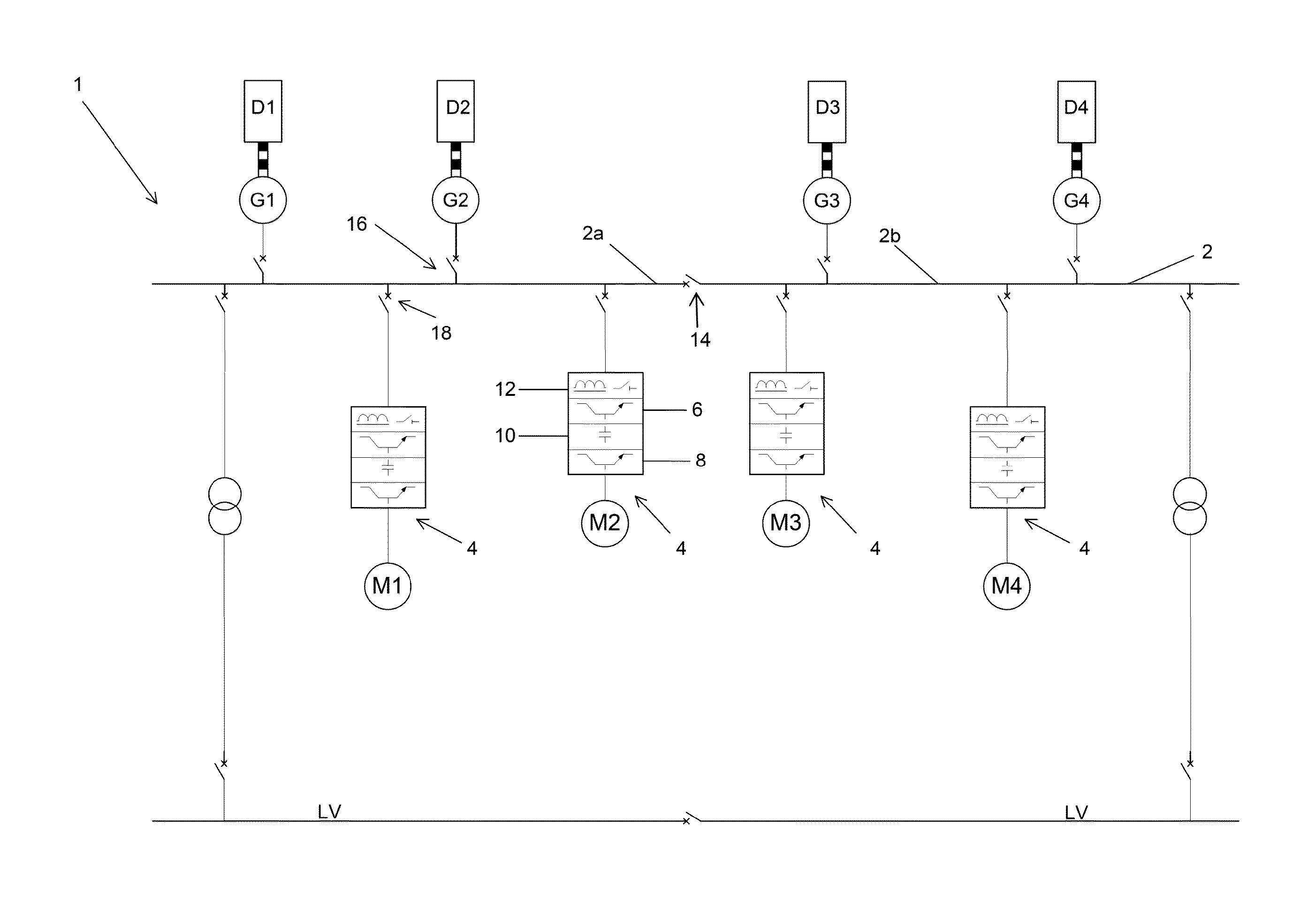
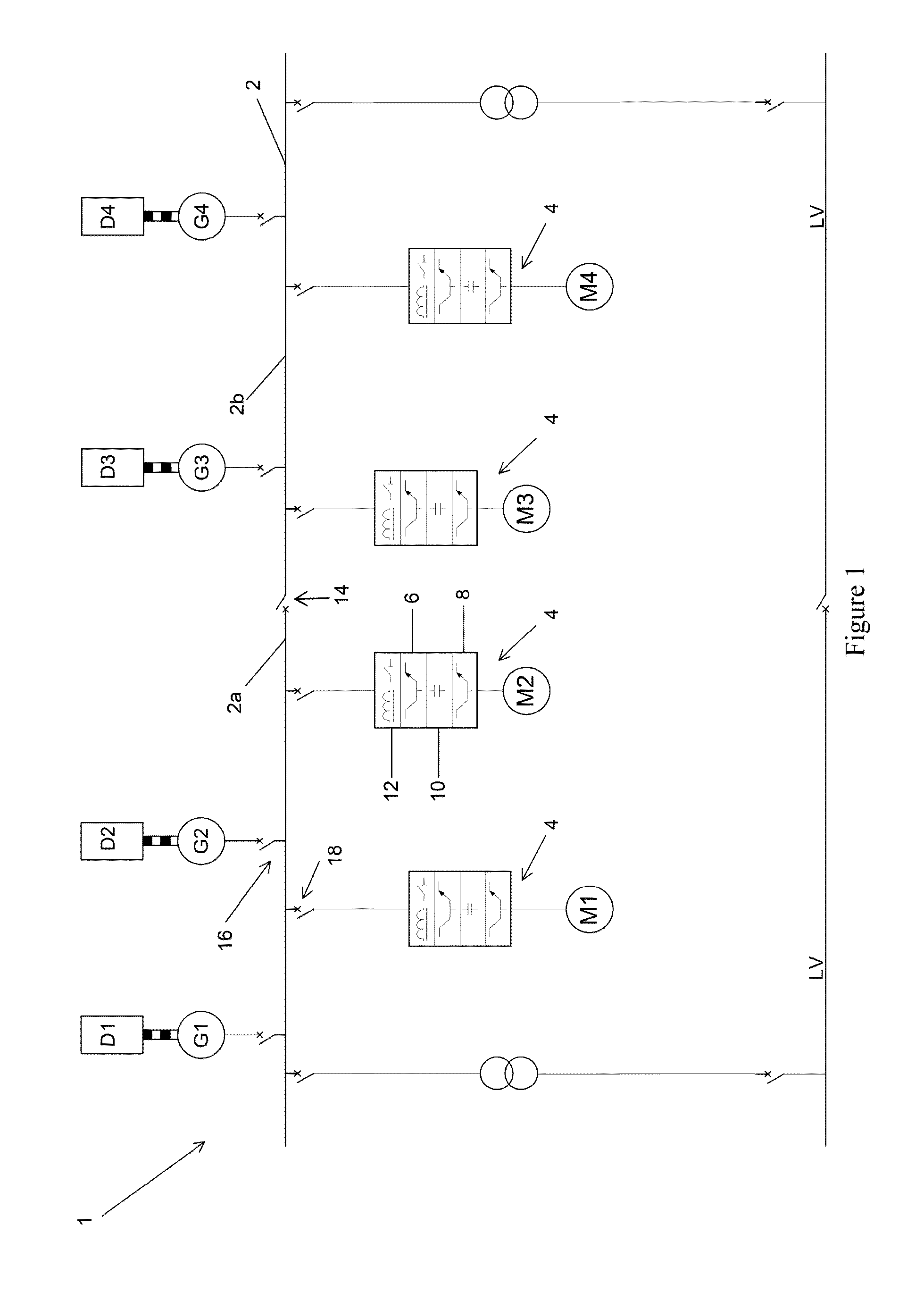
[0083]A marine power distribution and propulsion system 100 according to the present invention is shown in FIG. 8. Although the following description concentrates on systems for marine vessels, it will be readily appreciated that other power distribution systems can be implemented in a similar manner.

[0084]The overall marine power distribution and propulsion system 100 is similar to the one shown in FIG. 1 and it will be understood that any suitable number and type of ac generators, propulsion motors etc. can be used. Like components have been given the same labels or reference numerals.

[0085]A plurality of ac generators G1 . . . G4 provide ac power to a busbar 52 which carries a variable-frequency distribution voltage (e.g. 690 V but other system voltages can be used). The generators G1 . . . G4 are associated with diesel engines D1 . . . D4 but other types of prime mover can be used.

[0086]Electric propulsion motors M1 . . . M4 are connected to the busbar 52 by means of interposing...


PUM


Abstract

A power distribution system is described that does not rely on a fixed frequency and which therefore allows prime movers to run at different speeds in response to load demand, typically so that fuel consumption and / or harmful exhaust emissions is / are minimised. A marine power distribution and propulsion system can include an ac busbar adapted to carry a variable-frequency ac distribution voltage. A plurality of ac generators are connected to the busbar, each having an associated prime mover such as a diesel engine, turbine etc. A power management controller is adapted to vary the rotational speed of the prime movers with reference to the electrical load on the ac busbar such that the generators provide a variable frequency output during normal operation of the power distribution system. Such operation is to be contrasted with conventional distribution systems which have a fixed frequency.

Description

FIELD OF THE INVENTION[0001]The present invention relates to power distribution systems, and in particular to power distribution systems that are designed to operate with a variable system frequency depending on load demand. The present invention can optionally be implemented as a marine power distribution and propulsion systems that can be installed in any suitable marine vessel, either civilian or military.BACKGROUND OF THE INVENTION[0002]Power distribution systems are well known. In a typical arrangement of a marine power distribution and propulsion system shown in FIG. 1 a plurality of ac generators G1 . . . G4 provide ac power to a busbar or switchboard 2 which carries a distribution voltage such as 690 V. Each generator G1 . . . G4 is coupled to a prime mover such as a diesel engine D1 . . . D4.[0003]Electric propulsion motors M1 . . . M4 are connected to the busbar 2 by means of interposing power converters 4. The propulsion motors M1 . . . M4 can be of any suitable type and ...

Claims


Application Information

Patent Timeline
Patent Type & Authority Applications(United States)
IPC IPC(8): H02P9/04H02J3/40H02J3/46
CPCH02P9/04H02J3/46H02J3/40B63H23/24H02J3/466H02J2310/42H02M5/458B63H21/17
Inventor CLARKE, NICHOLAS JAMESCHILDS, JONATHAN
Owner GE ENERGY POWER CONVERSION TECH
Why Eureka
Try Eureka