Light emitting system and power control device thereof

a technology of power control device and light emitting system, which is applied in the direction of lighting apparatus, lighting sources, electrical apparatus, etc., can solve the problems of drop of forward voltage, inability to maintain desired color temperature and desired color rendering index, etc., and achieve stable color temperature and color rendering index.

Inactive Publication Date: 2014-01-09
NATIONAL CHI NAN UNIVERSITY
View PDF7 Cites 10 Cited by
  • Summary
  • Abstract
  • Description
  • Claims
  • Application Information

AI Technical Summary

Benefits of technology

[0008]Therefore, an object of the present invention is to provide a light emitting system that may have a relatively stable color temperature and a relatively stable color rendering index.

Problems solved by technology

When the LED is driven with a constant current, rise of the ambient temperature may result in drop of the forward voltage, so that the output power of the LED (=forward voltage×working current) drops with rise of the ambient temperature.
When each of the LEDs with different primary colors is driven by a corresponding conventional power control device, the power ratio thereamong may drift due to different drop levels among the LEDs, such that the desired color temperature and the desired color rendering index may not be maintained.

Method used


Image

  • Light emitting system and power control device thereof
  • Light emitting system and power control device thereof
  • Light emitting system and power control device thereof

Examples


Embodiment Construction

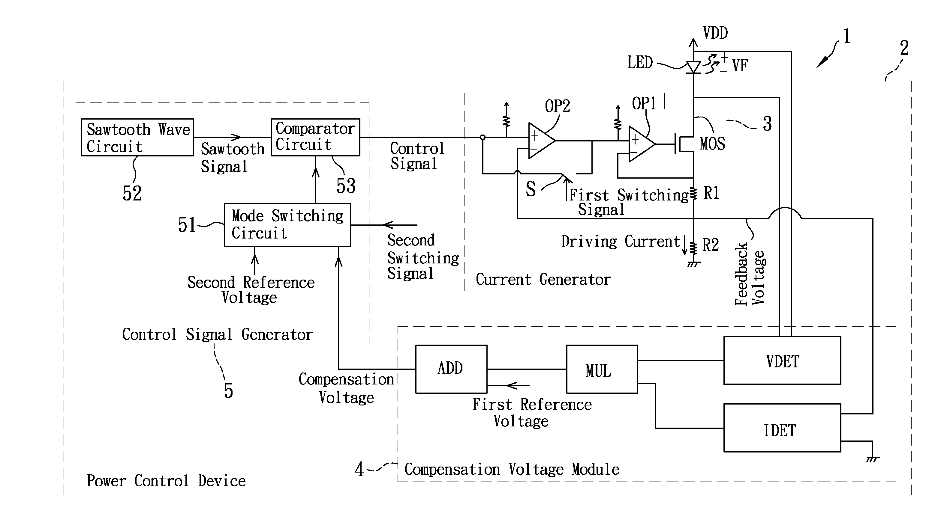
[0027]Referring to FIG. 3, the preferred embodiment of the light emitting system 1 according to this invention is shown to include a light emitting device LED and a power control device 2.

[0028]In this embodiment, the light emitting device LED is a light emitting diode device that has a forward voltage VF with a magnitude dependent on an ambient temperature (an ambient parameter) when driven with current, and that has an anode end for receiving a bias voltage VDD, and a cathode end.

[0029]The power control device 2 includes a current generator 3, a compensation voltage module 4, and a control signal generator 5.

[0030]The current generator 3 is coupled to the cathode end of the light emitting device LED and is disposed to receive a control signal. In this embodiment, the control signal is a pulse signal. The current generator 3 converts the control signal into a driving current (a pulse current) provided to the light emitting device LED. In this embodiment, the driving current has an ...


PUM


Abstract

A light emitting system includes a light emitting device having a forward voltage dependent on an ambient parameter, and a power control device including a current generator, a compensation voltage module, and a control signal generator. The current generator converts a control signal into a driving current for provision to the light emitting device, and provides a feedback voltage. The compensation voltage module obtains a compensation voltage according to the forward voltage, the feedback voltage, and a reference voltage. The control signal generator generates the control signal according to the compensation voltage for provision to the current generator.

Description

CROSS-REFERENCE TO RELATED APPLICATION[0001]This application claims priority to Taiwanese Application No. 101124417, filed on Jul. 6, 2012.BACKGROUND OF THE INVENTION[0002]1. Field of the Invention[0003]The invention relates to a light emitting system and a power control device thereof.[0004]2. Description of the Related Art[0005]FIG. 1 shows a conventional power control device adapted to receive a direct-current input voltage Vin and generate a working current to drive a light-emitting diode (LED). When the input voltage Vin is constant, the working current has a constant magnitude.[0006]However, the working current resulting from the direct-current input voltage Vin will increase temperature of the LED, and characteristics of the LED vary with ambient temperature. Referring to FIG. 2, a forward voltage of the LED varies with ambient temperature, and LEDs with different primary colors (i.e., red, green, and blue) follow different forward voltage-temperature curves. When the LED is ...

Claims


Application Information

Patent Timeline
Patent Type & Authority Applications(United States)
IPC IPC(8): H05B37/02
CPCH05B37/02H05B47/10H05B45/18
Inventor SUN, TAI-PINGSHIEH, HSIU-LICHAO, KUO-SHENG
Owner NATIONAL CHI NAN UNIVERSITY
Why Eureka
Try Eureka