Light module

a technology of light modules and modules, applied in the field of light modules, can solve the problems of high production costs and the integration of further light functions into such complex arrangements, and achieve the effects of low production cost, high optical quality, and simple structur

Inactive Publication Date: 2014-01-09
AUTOMOTIVE LIGHTING REUTLINGEN GMBH
View PDF8 Cites 25 Cited by
  • Summary
  • Abstract
  • Description
  • Claims
  • Application Information

AI Technical Summary

Benefits of technology

[0028]The primary optics device may include at least one convex lens. As a result, the desired representation of the source light segments in real intermediate images (intermediate light segments) can be achieved in a simple manner. It is also possible to use spherical lenses, which allow for a simple structure with high optical quality and which can be produced comparatively cost-effective.
[0029]In another embodiment, the first and / or the second primary optics device includes an optical element for correcting image defects. In particular, the optical element is provided in addition to an optical imaging element, for example, a convex lens. The optical imaging element has the purpose of producing the real intermediate image of the source light segments, whereas the previously mentioned optical element is able to correct image defects in combination with the imaging element. In this way, it is thus possible to avoid unwanted color edges of the light beam distribution by correcting the chromatic image defects already on the intermediate image surface. The optical element for correcting chromatic image defects could include an achromatic lens for correcting color image defects.
[0030]When the primary optics device includes multiple lenses, it is advantageous to provide the surfaces of the optical elements or lenses with an anti-reflection coating.

Problems solved by technology

The known solutions have the problem that the provision of uniform light beam distribution and the facilitation of antiglare high beam requires multiple headlamps, at least multiple light modules that have to be combined with and adjusted to one another.
This requires extensive coordination and adjustment of the individual components, which can result in high production costs.
Moreover, it poses a problem to integrate into such complex arrangements further light function, such as lateral illumination, daytime running lights, indicator lights or a low beam light or a dimmed light distribution.

Method used


Image

  • Light module
  • Light module
  • Light module

Examples


Embodiment Construction

[0059]In the following description identical or corresponding components are provided with the same reference numerals.

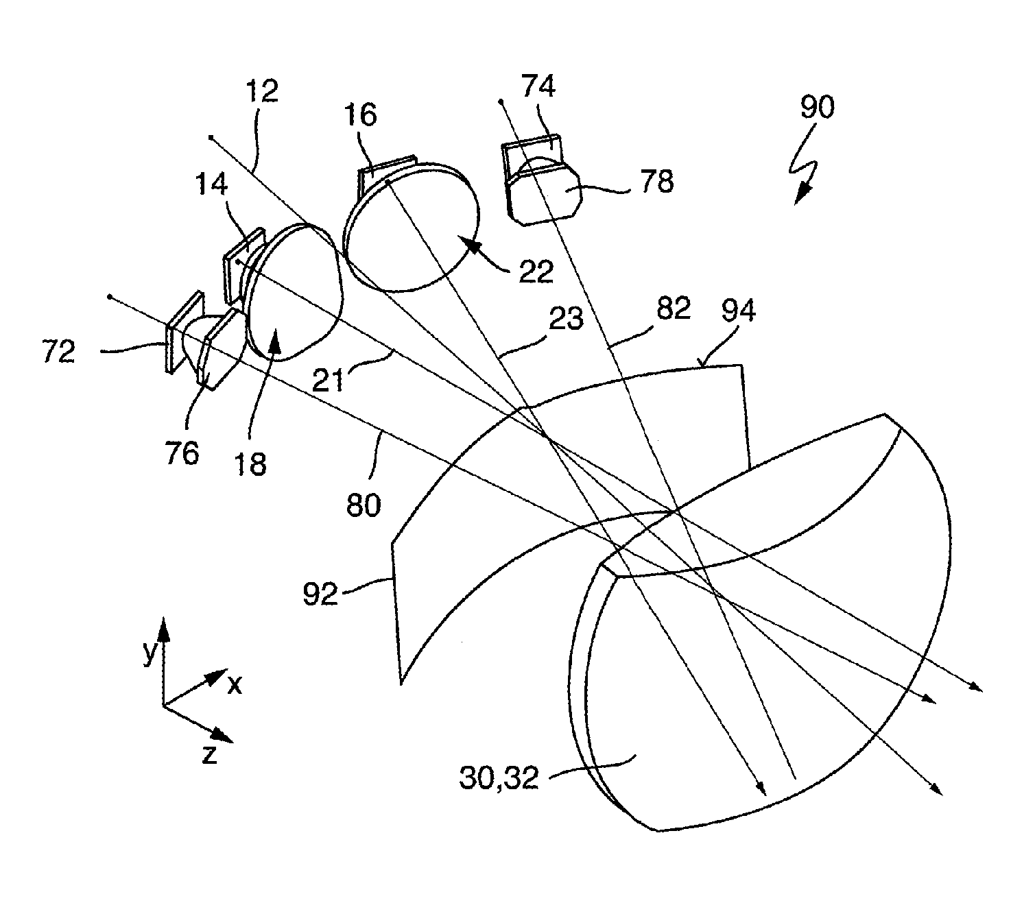
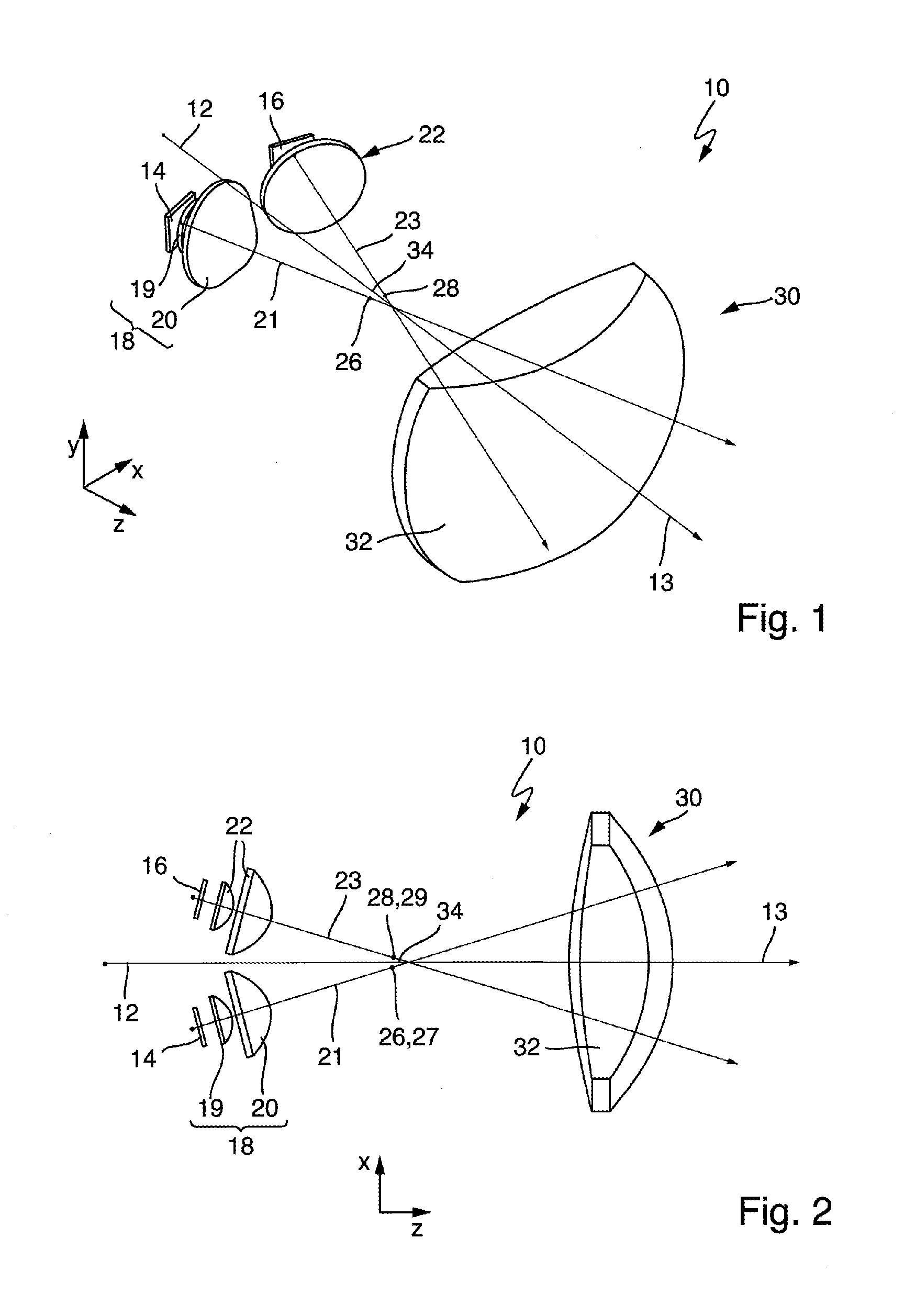
[0060]FIG. 1 shows a light module 10 of the present invention, which can be used, for example, in a motor vehicle headlamp for the purpose of providing a high beam. For the light module 10, an optical axis 12 has been defined which indicates a primary beam direction 13. For reasons of clarity, the light module 10 is shown without a housing, although any design of a housing can be provided.

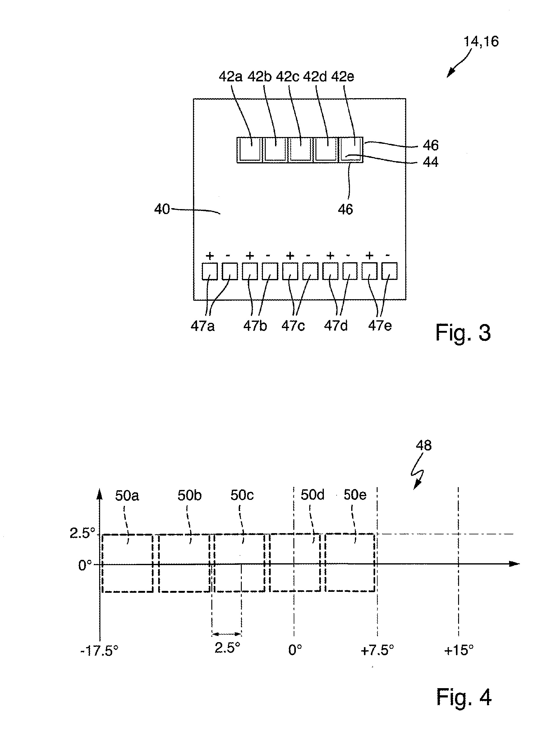
[0061]The light module 10 includes a first semiconductor light source 14 and a second semiconductor light source 16, which are described in more detail in the description of the embodiments shown in FIGS. 3 and 7. At any rate, each of the semiconductor light sources comprises a plurality of light-emitting diodes (LEDs) arranged in groups, wherein each LED of each semiconductor light source 14 or 16 is designed in such a way that it is possible to emit a source light segment assigne...


PUM


Abstract

A light module having a first and a second primary optics device wherein the individual LEDs of a first and a second semiconductor light source can be reproduced as real intermediate images on an intermediate image surface, wherein an intermediate image assigned to the first semiconductor light source is overlapping with at least one intermediate image assigned to a second semiconductor light source, and that a secondary optics device is arranged in such a way that the intermediate images can be projected as assigned light beam segments of the light beam distribution.

Description

CROSS-REFERENCE TO RELATED APPLICATION[0001]This application is based upon and claims priority to German Patent Application 10 2012 211 613.3 filed on Jul. 4, 2012.BACKGROUND OF INVENTION[0002]1. Field of Invention[0003]The invention relates to a light module for a lighting device for a motor vehicle. Such light modules are used as high beam headlights in motor vehicle headlamps.[0004]2. Description of the Related Art[0005]Normally, it is desired to achieve a light beam distribution with high homogeneity. Basically, strip-shaped areas of the light beam distribution should be avoided because they show different light because they may be considered to be annoying. On the other hand, as far as possible, the high beam headlights in motor vehicle headlamps should not have a glare.[0006]To this end, the EP 2 280 215 A2 describes a motor vehicle headlamp which comprises a plurality of LED light source modules for light transmission in basically parallel beam direction.[0007]Each LED light ...

Claims


Application Information

Patent Timeline
Patent Type & Authority Applications(United States)
IPC IPC(8): F21V5/08
CPCF21V5/08F21S41/143F21S41/147F21S41/255F21S41/26F21S41/663F21S41/153F21S41/151
Inventor HOSSFELD, WOLFGANG
Owner AUTOMOTIVE LIGHTING REUTLINGEN GMBH
Why Eureka
Try Eureka