Thin hollow backlights with beneficial design characteristics

a technology of design characteristics and backlights, applied in the field of extended area light sources, can solve the problem of achieve the effect of reducing the mass of the backlight, highly resistant to source failure, and only modest reduction of brightness uniformity over the output area of such a backligh

Inactive Publication Date: 2014-01-09
3M INNOVATIVE PROPERTIES CO
View PDF0 Cites 0 Cited by
  • Summary
  • Abstract
  • Description
  • Claims
  • Application Information

AI Technical Summary

Benefits of technology

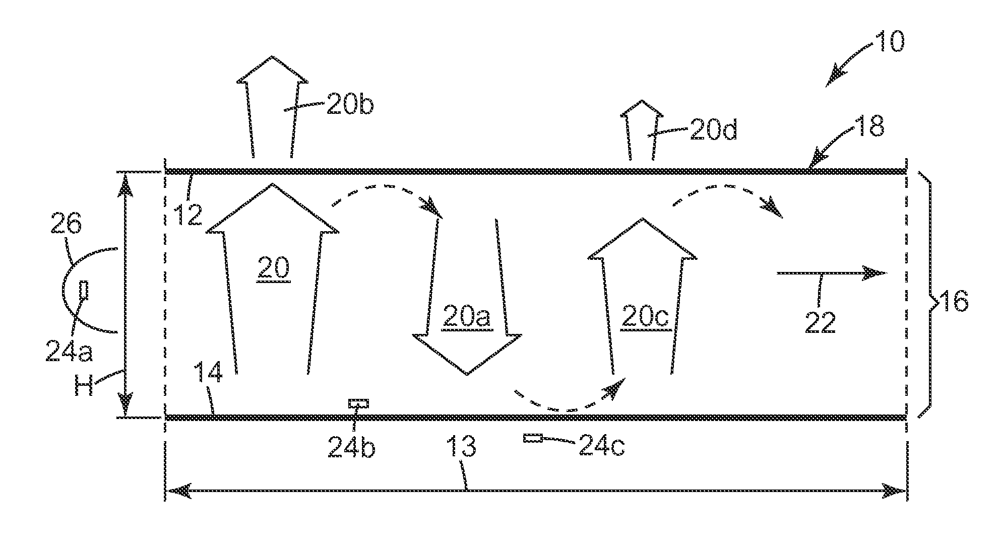
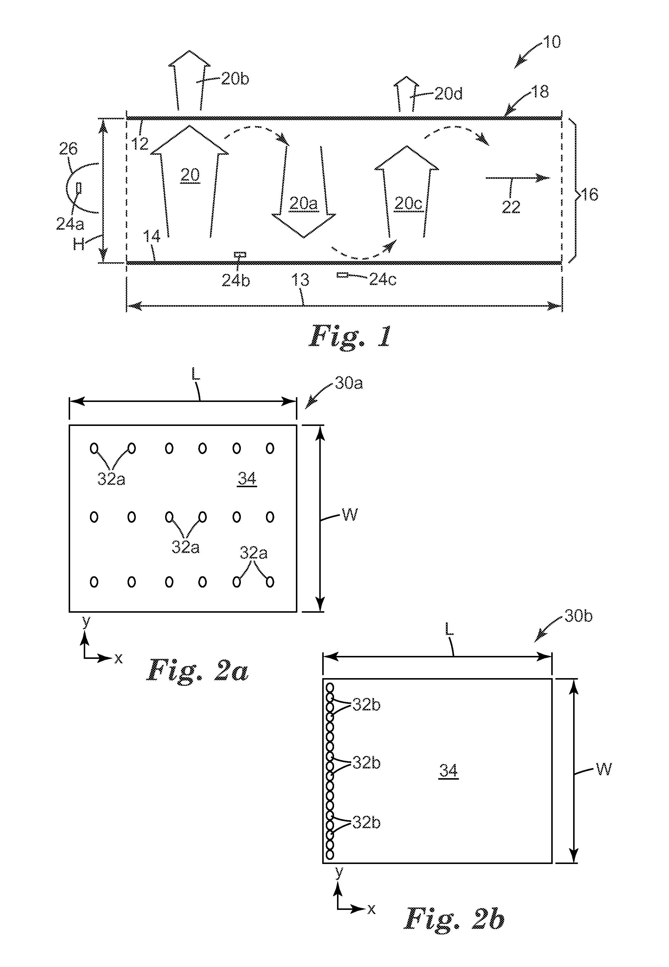
The patent is about an edge-lit backlight system that has a hollow recycling cavity with relatively large front and back reflectors. This design reduces the mass of the backlight compared to a solid light guide and ensures brightness uniformity even when individual light sources fail. The system also has low loss side reflectors that help to mix light in the cavity. As a result, the backlight is resistant to source failure and color variability and can maintain brightness uniformity even when one or more light sources are turned off.

Problems solved by technology

The brightness uniformity over the output area of such a backlight is only modestly diminished when individual light sources within the backlight degrade, fail, or are turned off.

Method used


Image

  • Thin hollow backlights with beneficial design characteristics
  • Thin hollow backlights with beneficial design characteristics
  • Thin hollow backlights with beneficial design characteristics

Examples


example 21a

[0112]the output region of the Edge-Lit, Hollow Backlight was covered by a reflective polarizer (APF mounted on an acrylic plate) which was placed over the output area of the backlight. All of the LEDs (red, green, and blue, except for the single green LED mentioned above, for a total of 4R 7G 4B) were turned on to produce white light. The backlight was bright close to the LEDs and visibly darker at the far end (away from the LEDs).

example 21b

[0113]the same configuration as for Example 21a was used, but only the green LEDs were powered (except for the single green LED mentioned above, for a total of 7G). The backlight appeared much brighter close to the LEDs and darker at the far end (away from the LEDs).

example 21c

[0114]the same configuration as for Example 21a was used, but only the four green LEDs of the right bank of LEDs were powered (for a total of 4G). The backlight appeared much brighter on the right side close to the LEDs and was darker at the far end (away from the LEDs) and also darker on the left side where the LEDs weren't lit.


PUM


Abstract

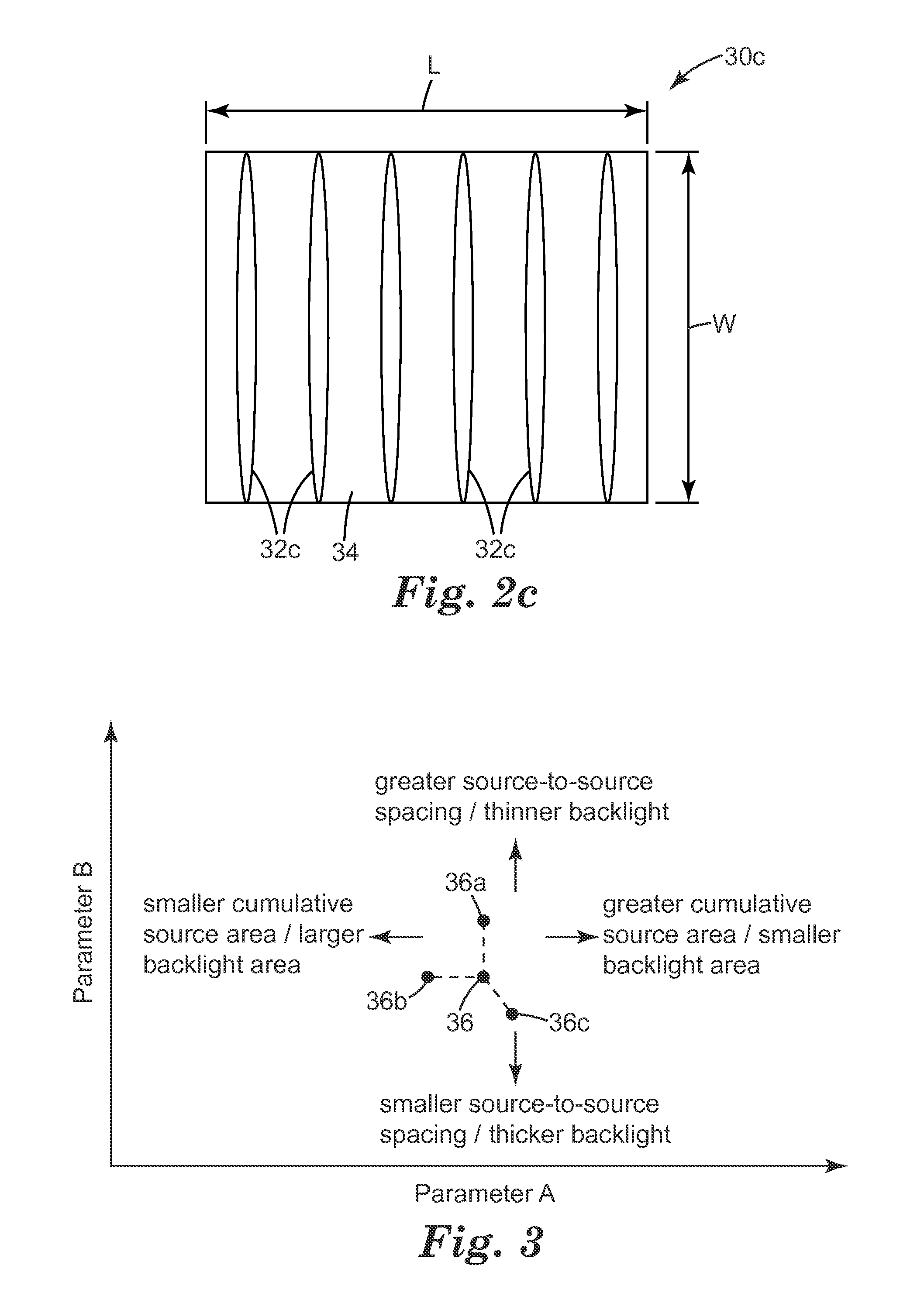
A front and back reflector are arranged to form a hollow light recycling cavity having an output region, and one or more light sources (e.g. LEDs) are disposed to emit light into the cavity. In one aspect, the back reflector has a design characterized by a first and second parameter. The first design parameter is a ratio of the collective emitting area of the light sources Aemit to the area of the output region Aout, and Aemit / Aout is preferably from 0.0001 to 0.1. The second design parameter is SEP / H, where H is the depth of the recycling cavity, and SEP is an average plan view source separation associated with the light sources. Other aspects of the disclosed extended area light sources are also described.

Description

RELATED APPLICATIONS[0001]The following U.S. patent and publications are incorporated herein by reference: U.S. Pat. No. 8,469,575; U.S. Patent Publication 2010 / 0238686; U.S. Patent Publication 2010 / 0165001; U.S. Patent Publication 2010 / 0165621.FIELD[0002]The present invention relates to extended area light sources suitable for illuminating a display or other graphic from behind, commonly referred to as backlights. The invention is particularly suited, but not necessarily limited, to backlights that emit visible light of substantially only one polarization state.BACKGROUND[0003]Historically, simple backlight devices included only three main components: light sources or lamps, a back reflector, and a front diffuser. Such systems are still in use for general purpose advertising signs and for indoor lighting applications.[0004]Over recent years, refinements have been made to this basic backlight design by adding other components to increase brightness or reduce power consumption, incre...

Claims


Application Information

Patent Timeline
Patent Type & Authority Applications(United States)
IPC IPC(8): F21V7/04
CPCF21V7/04G02B6/0055G02B6/0056G02B6/0068G02B6/0096G02F1/133603G02F1/133605G02F1/13362G02B6/00G02F1/1335
Inventor NEVITT, TIMOTHY J.HEBRINK, TIMOTHY J.WEBER, MICHAEL F.BIERNATH, ROLF W.FREIER, DAVID G.WHEATLEY, JOHN A.OUDERKIRK, ANDREW J.HOYLE, CHARLES D.DERKS, KRISTOPHER J.
Owner 3M INNOVATIVE PROPERTIES CO
Why Eureka
Try Eureka