Method for craneless wind turbine blade handling via a turbine hub

Active Publication Date: 2014-01-09
VESTAS WIND SYST AS
View PDF4 Cites 41 Cited by
  • Summary
  • Abstract
  • Description
  • Claims
  • Application Information

AI Technical Summary

Benefits of technology

[0036]In wind turbines having two, four, six and so on blades, there will due to reasons of symmetry, an upper blade, other than the one which is going to be mounted or dismounted downwardly, will be right above the one to be mounted or dismounted, whereby an anchoring frame is advantageously attached to e.g. the fastening bolts of said upper blade. This alleviates the need for having other means in the hub to attach to or create such means e.g. by drilling mounting holes. In wind turbines having three blade, the two blades, other than the one which is going to be mounted or dismounted, will be in symmetrical position, where a virtual line connecting fastening bolts or engagement portions for fastening bolts will be horizontal and very well suited for mounting opposite ends of an anchoring frame to supporting at least one pulley, guiding a wire to lift or lower a blade. Again, alleviating a need for providing other means to attach such an anchori

Problems solved by technology

When wind turbines are erected it is normal and feasible to use a large mobile crane, although such use is costly and may involve problems in getting the crane to the erection site.
In case a single turbine blade, or a limited number of blades, have to be dismounted and refitted, e.g. in a rare situation for repair or replacement, the cost of sending a mobile crane is relatively very high as the cost is at a similar scale whether one blade has to be taken up and down or a whole turbine is to erected.
This requires a tripod-like frame st

Method used


Image

  • Method for craneless wind turbine blade handling via a turbine hub
  • Method for craneless wind turbine blade handling via a turbine hub
  • Method for craneless wind turbine blade handling via a turbine hub

Examples


Embodiment Construction

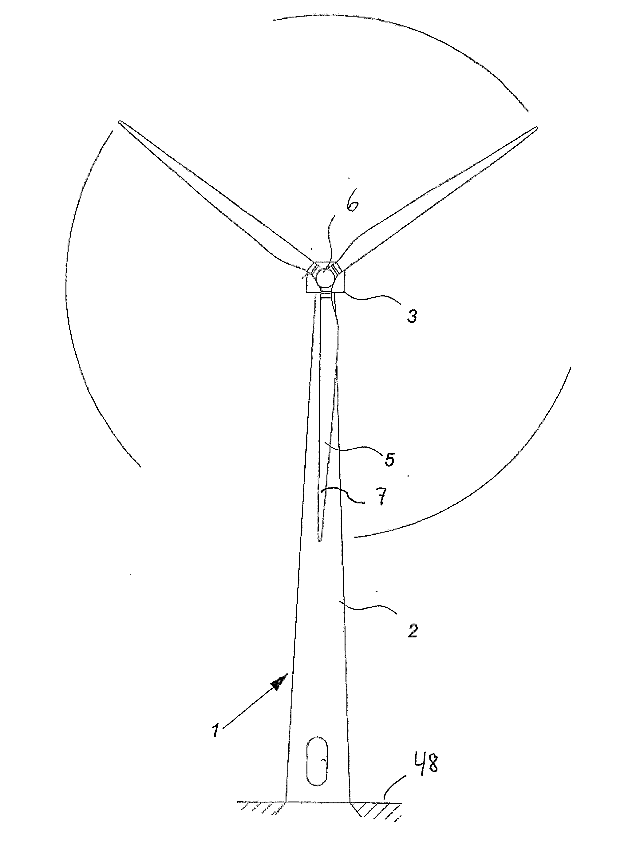
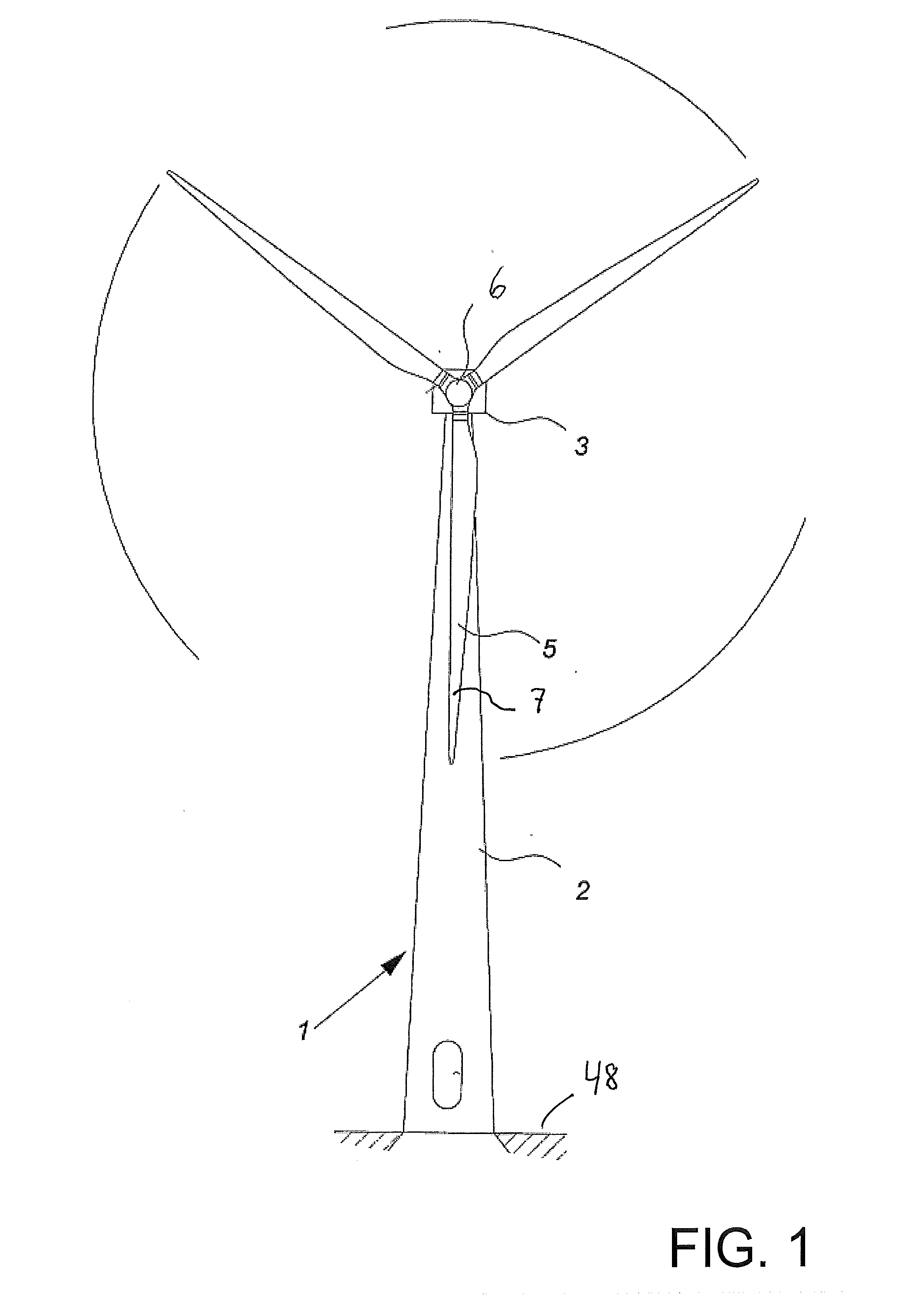
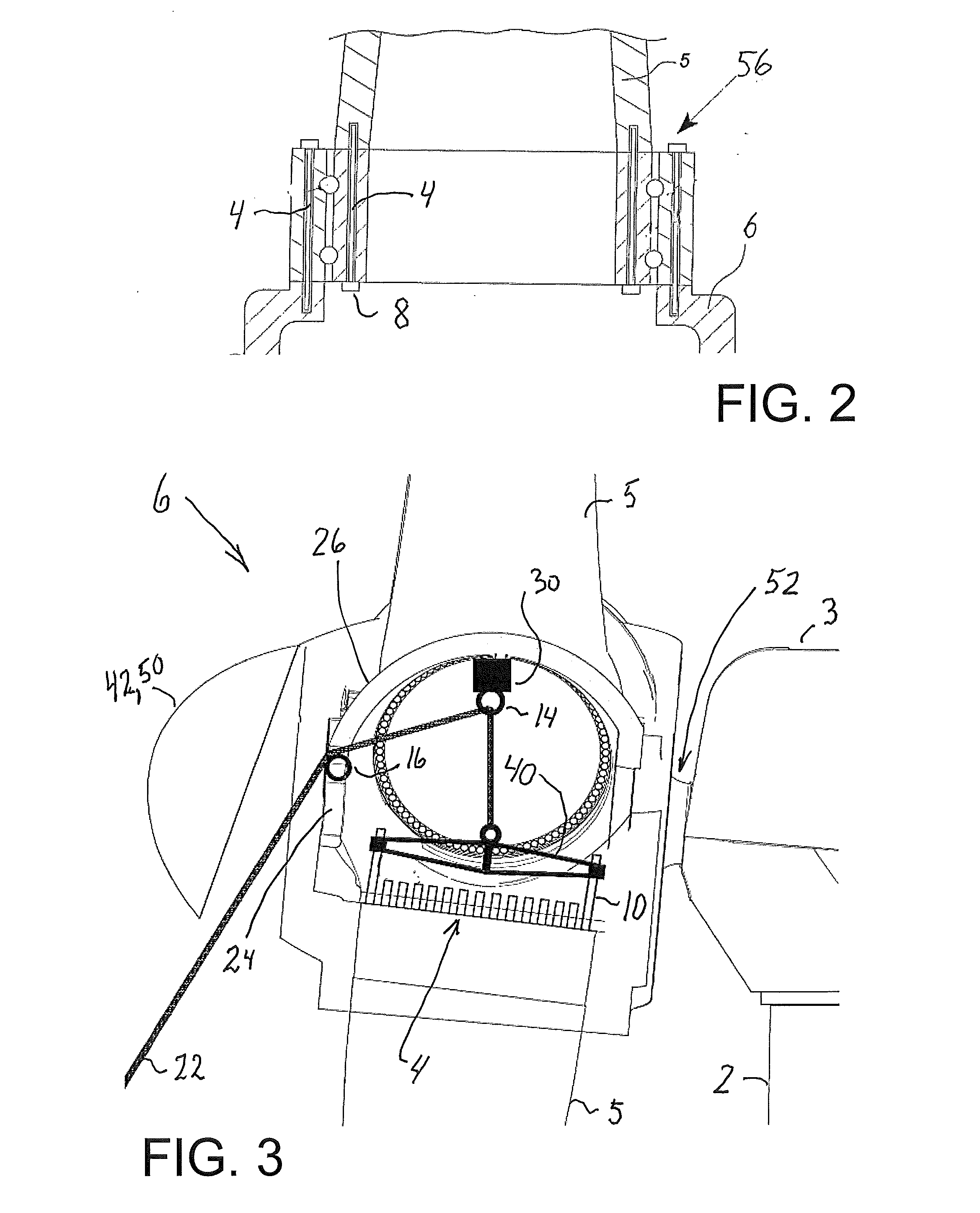
[0052]The wind turbine 1 of a well known modern type shown in FIG. 1 generally comprises a nacelle 3 mounted with a hub 6. Turbine blades 5 with blade tips 7 are mounted on the hub 6. The nacelle 3 is mounted on the top of a tower 2. The hub 6 is mounted to the nacelle 3 typically via main shaft 52 (shown in FIG. 2). Typically an electrical generator (not shown) is housed within the nacelle 3 and is driven by rotation of the hub 6 harvesting wind energy from the blades 5 to generate electrical power, but other types of power and / or energy or input / energy for physical or chemical processes, e.g. for the production of hydrogen, as well as heating or cooling may also be the objective. The wind turbine 2 is normally placed on the ground 48 at in offshore locations. The inventive aspects and concepts described in this document and appended drawings may be used for both on land as well as offshore use. As explained above the is a need for dismounting and mounting blades 5 from a hub 6 att...


PUM

PropertyMeasurementUnit
Pressureaaaaaaaaaa

Abstract

The invention involves craneless dismounting and/or mounting a vertically arranged wind turbine blade from a wind turbine generator hub mounted to a nacelle placed on a tower, said hub being arranged for having a number of blades attached. The method comprises mounting a number of bolt-like extensions in positions, where fastening bolts have been removed or could be received. These extensions are much longer than the fastening bolts, so that the blade may be handled using the extensions to a position where a lifting yoke may be attached or detached, either for lowering or lifting the blade. The method may be performed without at separate crane and is particularly useful in relation to blade maintenance, repair or replacement at remote wind turbine sites which would incur high costs for a mobile crane. Moreover, the method may be performed without having personnel going outside the hub or nacelle, but can stay at the ground and within the hub.

Description

TECHNICAL FIELD[0001]The present invention relates to a method of craneless dismounting and mounting a wind turbine blade from and to a hub, which is a structure arranged for having a number of blades attached to it and transferring energy from rotation of the blades to a nacelle, arranged on the top of a tower structure, for converting harvested energy from the wind to e.g. electrical energy via an electrical generator. The invention further relates to a wind turbine having at least one turbine blade mounted or dismounted according to the method.BACKGROUND[0002]When wind turbines are erected it is normal and feasible to use a large mobile crane, although such use is costly and may involve problems in getting the crane to the erection site. Erection sites are often remote and difficult to access, but since a tower, and a nacelle, a hub and blades etc. must all be lifted up for installation a mobile crane with a lifting yoke is normally preferred for eased and quick installation. The...

Claims


Application Information

Patent Timeline
IPC IPC(8): F01D5/30
CPCF01D5/30B66C1/108F03D13/10F03D80/50F05B2240/916Y02E10/72Y02E10/728Y10T29/49318
Inventor NIELSEN, KENNET HVID
Owner VESTAS WIND SYST AS
Why Eureka
Try Eureka