Power supply device and vehicle equipped therewith

a power supply device and power supply technology, applied in hybrid vehicles, battery/fuel cell control arrangements, cell components, etc., can solve problems such as corrosion and unintended electrical conduction, and achieve the effect of high reliability

Inactive Publication Date: 2014-01-09
SANYO ELECTRIC CO LTD
View PDF3 Cites 57 Cited by
  • Summary
  • Abstract
  • Description
  • Claims
  • Application Information

AI Technical Summary

Benefits of technology

[0008]In order to achieve the above-mentioned object, the power supply device according to a first aspect of the present invention is a power supply device including a battery cell stack constructed of a plurality of stacked battery cells, and a cooling pipe disposed in a thermally coupled state over one surface of the battery cell stack, the cooling pipe being adapted to perform a heat exchange with the battery cell stack by allowing a refrigerant to flow inside the pipe, wherein a plurality of rows of the cooling pipes are sp

Problems solved by technology

When such dew condensation occurs, an unintended electrical

Method used


Image

  • Power supply device and vehicle equipped therewith
  • Power supply device and vehicle equipped therewith
  • Power supply device and vehicle equipped therewith

Examples


embodiment 1

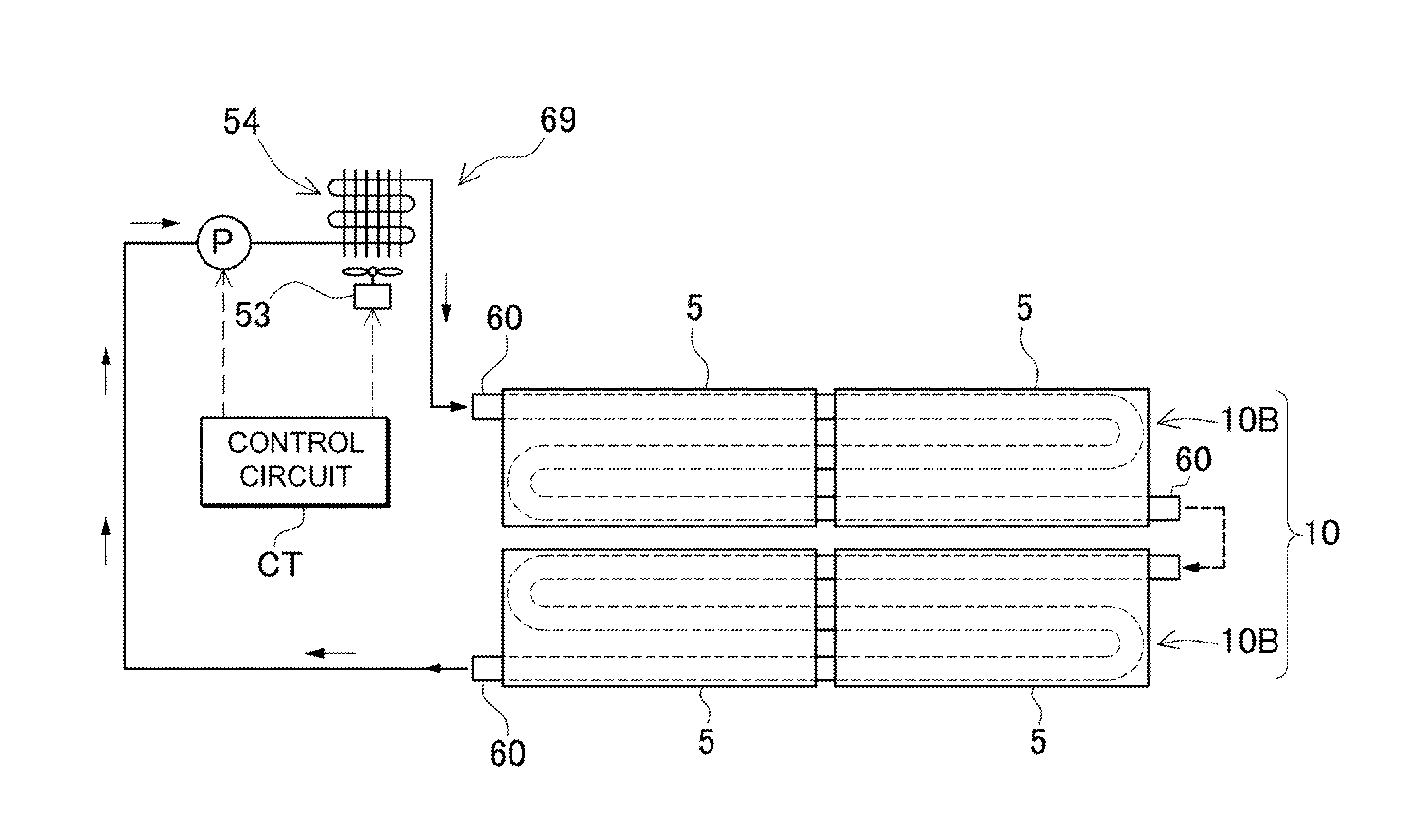
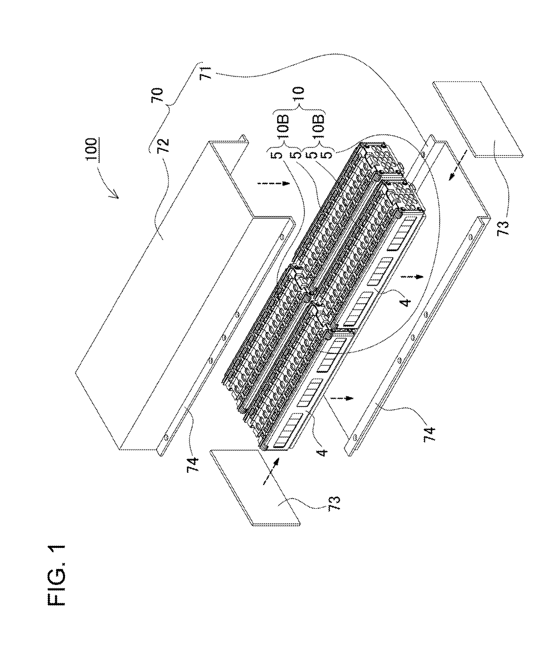
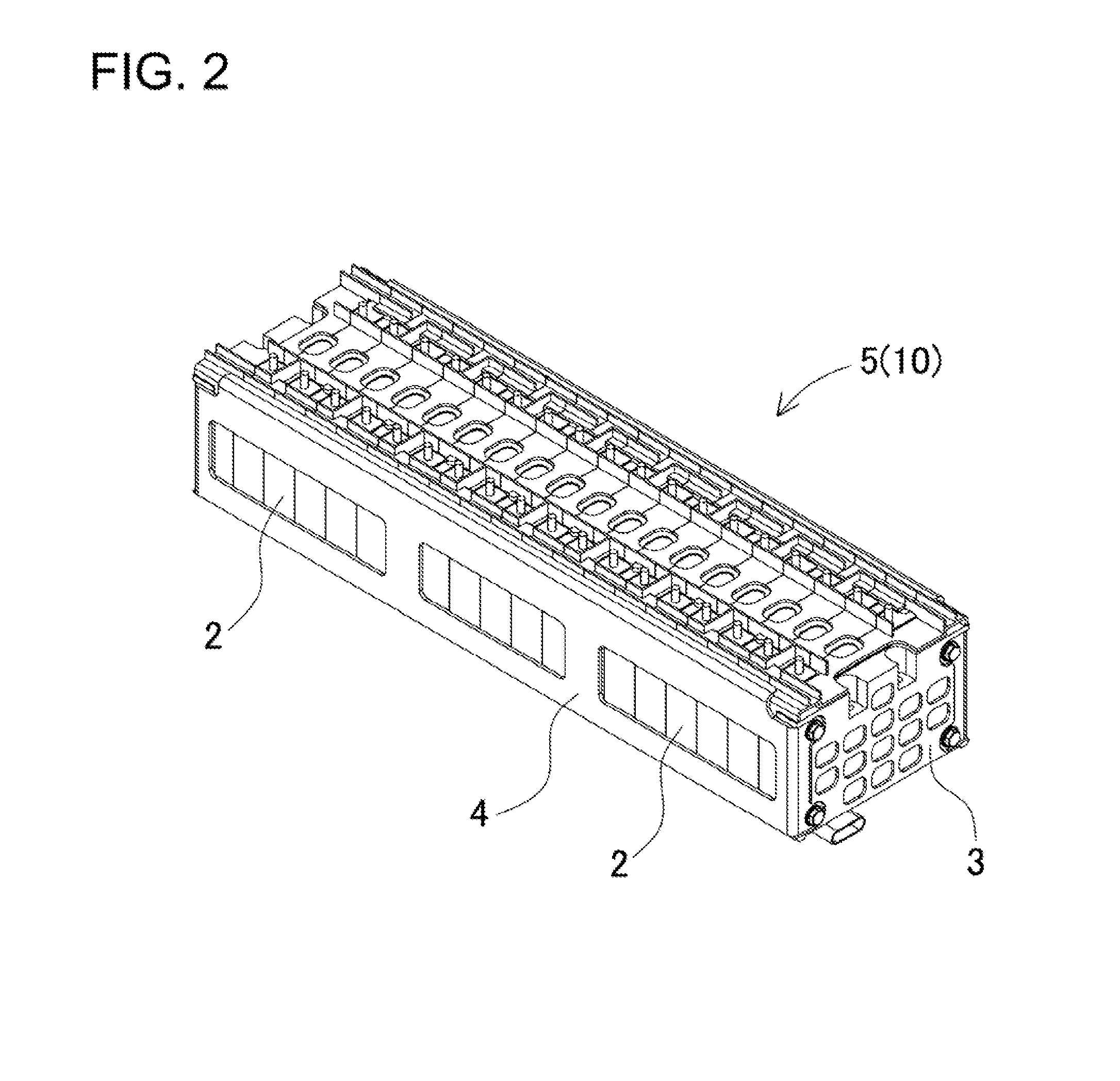
[0043]Referring to FIG. 1 through FIG. 3, a description shall now be made on an example in which the power supply device 100 according to Embodiment 1 of the present invention is applied as a power supply device mounted on a vehicle. In these drawings respectively, FIG. 1 is an exploded perspective view of the power supply device 100; FIG. 2 is a perspective view of the battery cell stack 5 as shown in FIG. 1; and FIG. 3 is an exploded perspective view of the battery cell stack 5 as shown in FIG. 2. The power supply device 100 is mainly mounted on an electrically driven vehicle such as a hybrid car and an electric car, and is used as an electric power source for driving a vehicle, by supplying electric power to a driving motor of the vehicle. It should be added that the inventive power supply device can be used for an electrically driven vehicle other than a hybrid car and an electric car, and can also be used for purposes in which a larger output power is required besides the elect...

embodiment 2

[0067]In the above-mentioned example, the heat insulating member 14 is filled between the cooling pipes 60. However, the space between the cooling pipes can also be covered by the cover casing. Such example is shown in FIG. 8a as Embodiment 2. This illustration is a schematic sectional view of the power supply device 200 in accordance with Embodiment 2. The cover casing 16B is provided with a surface covering portion 17 to cover one surface of the battery cell stack 5, being located between the spaced-apart cooling pipes 60 at the bottom surface. The surface covering portion 17 is provided on the bottom surface of the cover casing 16B, the cooling pipe 60 is designed to be disposed in an open portion being slit between the surface covering portions 17, and thus the surface covering portion 17 can be inserted in between the cooling pipes 60. For this purpose, the size of the surface covering portion 17 is so formed as to be insertable into the space between the cooling pipes. Further...

embodiment 3

[0071]Further, in the above-mentioned example, the cover casing 16B is provided with the extension 16b on the side of the cooling pipe 60 on the bottom surface of the battery cell stack 5, which reduces the amount of used resin. Conversely, such extension is eliminated for a configuration that the entire bottom surface of the battery cell stack is covered by the heat insulating member. Such configuration is shown as Embodiment 3 in FIG. 9. FIG. 9 is a schematic sectional view of the power supply device 300 in accordance with the Embodiment 3. In this configuration, although an amount of used resin increases, the configuration has the advantages in that the bottom surface of the cover casing 16C is fully opened, that a work of storing the battery cell stack 5 in the cover casing 16C can be readily carried out, and that the work involved in a manufacturing process can be simplified.


PUM


Abstract

A power supply device includes a battery cell stack (5) constructed of a plurality of stacked, rectangular battery cells, and a cooling pipe (60) disposed in a thermally coupled state over one surface of the battery cell stack (5), the cooling pipe (60) being adapted to perform a heat exchange with the battery cell stack (5) by allowing a refrigerant to flow inside the pipe, wherein a plurality of rows of the cooling pipes (60) are spaced apart from each other over the one surface of the battery cell stack (5), and a resin member is placed between the spaced-apart cooling pipes (60) such that the one surface of the battery cell stack (5) is covered in a sealed state.

Description

BACKGROUND OF THE INVENTION[0001]1. Field of the Invention[0002]The present invention relates generally to power supply devices of a large current and also relates to vehicles equipped with such power supply device. The power supply devices are used for driving a motor mounted on a vehicle, such as a hybrid car and an electric car, being also used for an electric storage at homes and factories where a large current is used.[0003]2. Description of the Related Art[0004]There has been a need for a power supply device with a higher output, such as a battery pack used for a vehicle. In such power supply device, a multitude of battery cells are interconnected in series to increase output voltage and output power. When electrically charged and discharged at a large current, the battery cells heat up. In particular, as the number of battery cells used increase, an amount of heat generation also increases. As such, a heat radiation mechanism is needed for efficiently conducting the heat rele...

Claims


Application Information

Patent Timeline
IPC IPC(8): H01M10/50H01M50/209H01M50/278
CPCH01M10/5004H01M10/5016B60L1/003B60L2210/30B60L2210/40H01M10/625H01M10/647H01M10/6556H01M10/6552H01M10/6555H01M10/6554H01M10/613H01M10/658B60L50/62B60L50/16B60L58/21B60L58/26B60L50/64Y02T10/62Y02T10/70Y02T10/72Y02T10/7072Y02E60/10H01M50/209H01M50/278
Inventor HASHIMOTO, HIROYUKITSUCHIYA, MASAKIASAI, YASUHIROSETO, TAKASHIKOMORIYA, TAKAHIDE
Owner SANYO ELECTRIC CO LTD
Why Eureka
Try Eureka