Electromagnetic Bone Conduction Hearing Device

a bone conduction and hearing device technology, applied in the field of medical implants, can solve problems such as impaired hearing

Active Publication Date: 2014-01-09
MED EL ELEKTROMEDIZINISCHE GERAETE GMBH
View PDF3 Cites 44 Cited by
  • Summary
  • Abstract
  • Description
  • Claims
  • Application Information

AI Technical Summary

Benefits of technology

[0027]Although various exemplary embodiments of the invention have been disclosed, it should be apparent to those skilled in the art that various changes and modifications can be made which will achieve some of the advantages of the invention without departing from the true scope of the invention.

Problems solved by technology

Hearing is impaired when there are problems in the ability to transduce external sounds into meaningful action potentials along the neural substrate of the cochlea.

Method used


Image

  • Electromagnetic Bone Conduction Hearing Device
  • Electromagnetic Bone Conduction Hearing Device
  • Electromagnetic Bone Conduction Hearing Device

Examples


Embodiment Construction

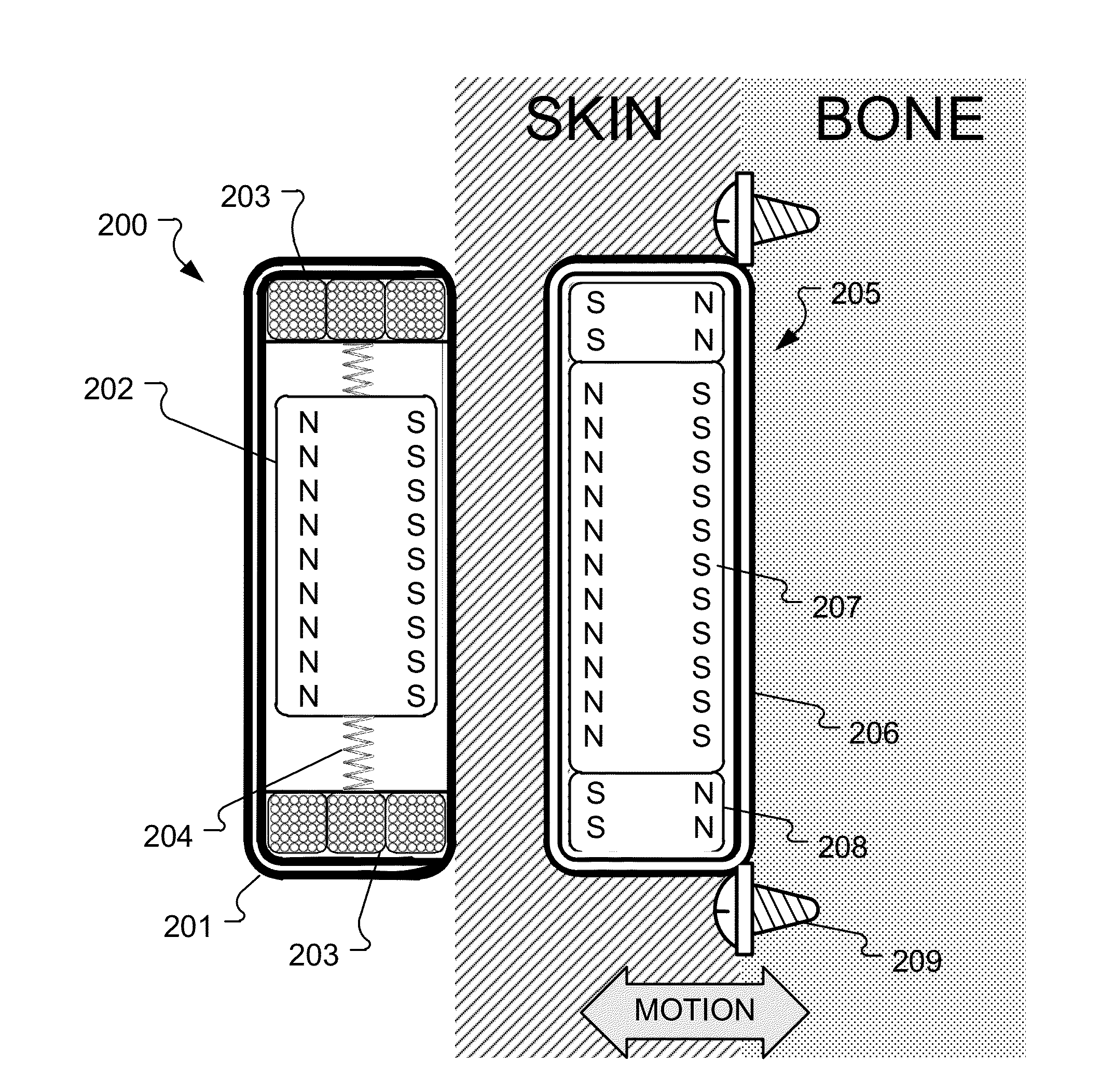
[0016]Conventional bone conduction implant arrangements may not optimally exploit the relatively large masses of the magnets that are used. Embodiments of the present invention are directed to an external component for a bone conduction hearing implant that better harnesses the inertial masses involved.

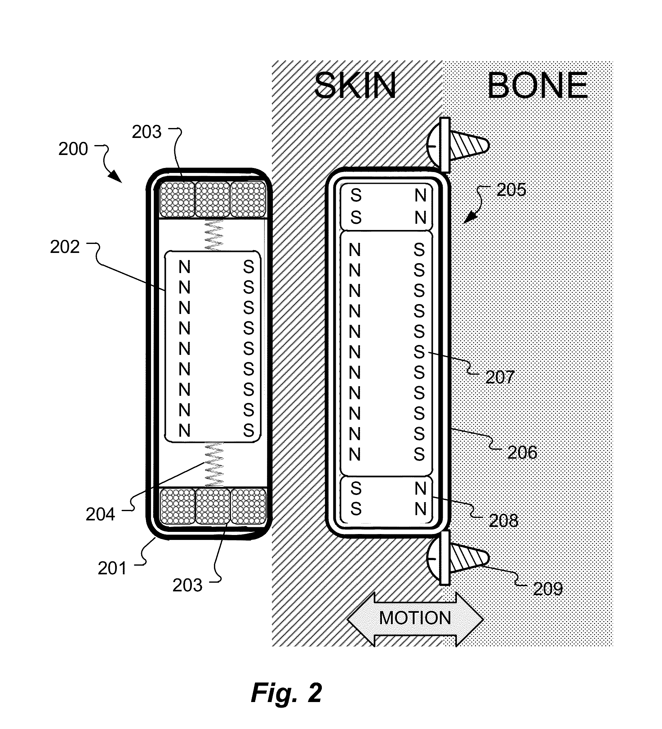
[0017]FIG. 2 shows various structural elements of an external component 200 having an external housing 201 that is fixedly attached on the skin of a hearing implant patient over an implanted bone conduction hearing transducer 205. The implanted transducer 205 is fixedly attached to the skull bone of the patient by bone attachment screws 209. An electromagnetic drive coil arrangement 203 is fixed within the external housing 201 for conducting electrical current to develop electromagnetic drive signals (generated by an external signal processor, not shown) for the implanted hearing transducer 205. A cylindrical attachment magnet 202 is suspended with the external housing 201 by a flexib...


PUM


Abstract

An external component for a bone conduction hearing implant is described. An external housing is fixedly attached on the skin of a hearing implant patient over an implanted bone conduction hearing transducer. An electromagnetic drive coil arrangement is fixed within the external housing for conducting electrical current to develop electromagnetic drive signals. An attachment magnet arrangement is suspended with the external housing by a flexible spring arrangement and magnetically coupled to the drive coil arrangement and to a corresponding implant magnet arrangement within the implanted bone conduction transducer. The electromagnetic drive signals magnetically interact with the attachment magnet arrangement which reacts by vibrating on the spring arrangement and magnetically interacting with the implant magnet arrangement to generate a bone conduction vibration signal by the implanted bone conduction hearing transducer for perception by the patient as sound.

Description

[0001]This application claims priority from U.S. Provisional Patent 61 / 669,161, filed Jul. 9, 2012, which is incorporated herein by reference.FIELD OF THE INVENTION[0002]The present invention relates to medical implants, and more specifically to a novel bone conduction hearing implant system.BACKGROUND ART[0003]A normal ear transmits sounds as shown in FIG. 1 through the outer ear 101 to the tympanic membrane 102 which moves the ossicles of the middle ear 103 that vibrate the oval window 106 and round window 107 membranes of the cochlea 104. The cochlea 104 is a long narrow duct wound spirally about its axis for approximately two and a half turns. The cochlea 104 forms an upright spiraling cone with a center called the modiolar where the spiral ganglion cells of the cochlear nerve 105 reside. In response to received sounds transmitted by the middle ear 103, the fluid-filled cochlea 104 functions as a transducer to generate electric pulses which are transmitted by the cochlear nerve ...

Claims


Application Information

Patent Timeline
Patent Type & Authority Applications(United States)
IPC IPC(8): H04R25/00
CPCH04R25/60A61N1/08A61N1/3718A61N1/375H04R25/606A61N1/36036A61N1/37518H04R11/02
Inventor BALL, GEOFFREY R.
Owner MED EL ELEKTROMEDIZINISCHE GERAETE GMBH
Why Eureka
Try Eureka