MRI-Safe Implant Magnet with Angular Magnetization

Active Publication Date: 2014-01-09
MED EL ELEKTROMEDIZINISCHE GERAETE GMBH
View PDF20 Cites 64 Cited by
  • Summary
  • Abstract
  • Description
  • Claims
  • Application Information

AI Technical Summary

Benefits of technology

[0008]In further specific embodiments, the magnetic axis may be angled away from the axis of symmetry at an angle of more than 10 degrees and less than 30 degrees, e.g., at an angle o

Problems solved by technology

One problem arises when the patient undergoes Magnetic Resonance Imaging (MRI) examination.
Among other things, this may damage the adjacent tissue in the patient.
In addition, the external magnetic field B from the MRI may reduce or remove the magnetization m of the implant magnet 202 so that it may no longer be strong enough to hold the external transmitter housing in proper position.
The implant magnet 202 may also cause imaging artifacts in the MRI image, there may be induced voltages in the receiving coil, and hearing artifacts due to the interaction of the external magnetic field B of the MRI with the implante

Method used


Image

  • MRI-Safe Implant Magnet with Angular Magnetization
  • MRI-Safe Implant Magnet with Angular Magnetization
  • MRI-Safe Implant Magnet with Angular Magnetization

Examples


Example

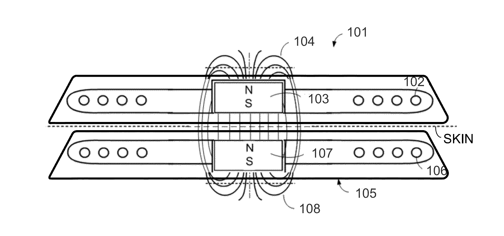
[0015]Various embodiments of the present invention are directed to a magnetic arrangement for an implantable system for a recipient patient which is compatible with MRI systems. Unlike a conventional implant magnet that has a magnetization direction along its axis of symmetry (resulting in magnetic poles on each of the circular disk surfaces), and in contrast with the design described in U.S. Patent Publication 20110264172 where the implant magnet has a magnetization direction perpendicular to its axis of symmetry, the implant magnet described herein has an angular or slanted magnetization direction along a magnetic axis that angled away from the axis of symmetry at a limited angle.

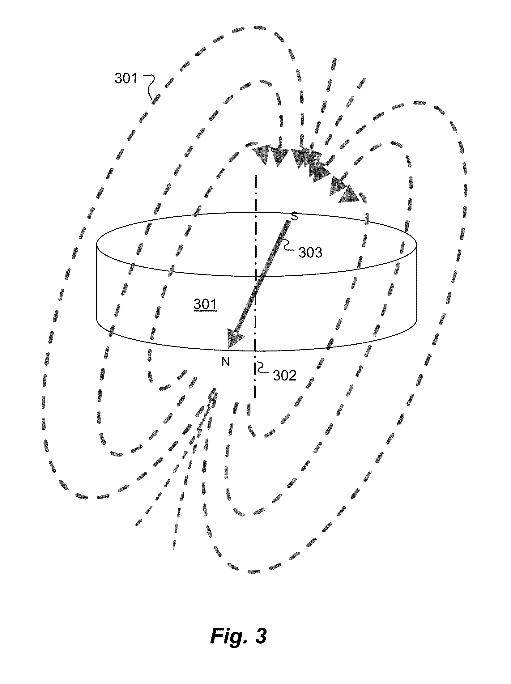
[0016]FIG. 3 shows a cylindrical implant magnet 300 having a magnetic field 301 an angular magnetization direction 303 according to an embodiment of the present invention. The angular magnetization direction 303 (that is, the magnetic dipole orientation) is at a slanted angle to the center cylinder axis o...


PUM


Abstract

A magnetic arrangement is described for an implantable system for a recipient patient. An implantable coil housing contains a signal coil for transcutaneous communication of an implant communication signal. Freely rotatable within the coil housing is a cylindrical implant magnet for transcutaneous magnetic interaction with a corresponding external attachment magnet. The implant magnet has a central cylinder axis of symmetry, and a magnetization direction along a magnetic axis angled away from the axis of symmetry at a non-zero angle less than 45 degrees.

Description

[0001]This application claims priority from U.S. Provisional Patent Application 61 / 667,474, filed Jul. 3, 2012, which is incorporated herein by reference.FIELD OF THE INVENTION[0002]The present invention relates to implantable medical devices, and specifically, to magnetic elements in such devices that allow for magnetic resonance imaging.BACKGROUND ART[0003]Some hearing implants such as Middle Ear Implants (MEI's) and Cochlear Implants (CI's) employ attachment magnets in the implantable part and an external part to hold the external part magnetically in place over the implant. For example, as shown in FIG. 1, a typical cochlear implant system may include an external transmitter housing 101 containing transmitting coils 102 and an external attachment magnet 103. The external attachment magnet 103 has a conventional cylindrical disk-shape and a north-south magnetic dipole having an axis that is perpendicular to the skin of the patient to produce external magnetic field lines 104 as s...

Claims


Application Information

Patent Timeline
IPC IPC(8): A61N1/372
CPCA61N1/37229A61N1/3718A61N1/36032A61N1/36036A61N1/36038
Inventor ZIMMERLING, MARTIN
Owner MED EL ELEKTROMEDIZINISCHE GERAETE GMBH
Why Eureka
Try Eureka