Cleavage method, rotor manufacturing method, and cleavage apparatus

a technology of rotor manufacturing and cleavage method, which is applied in the manufacture of stator/rotor bodies, metal working apparatuses, and solid insulation. it can solve the problems of long work time, long work time, and cost increase, and achieve the effect of preventing depression or caving in the surface, shortening the unit time, and cost reduction

Inactive Publication Date: 2014-01-16
TOYOTA JIDOSHA KK
View PDF6 Cites 8 Cited by
  • Summary
  • Abstract
  • Description
  • Claims
  • Application Information

AI Technical Summary

Benefits of technology

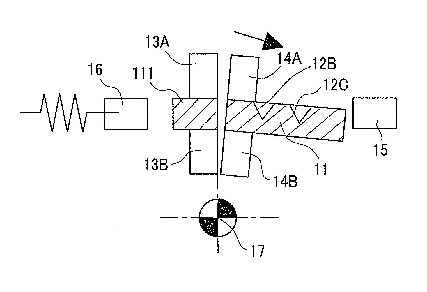
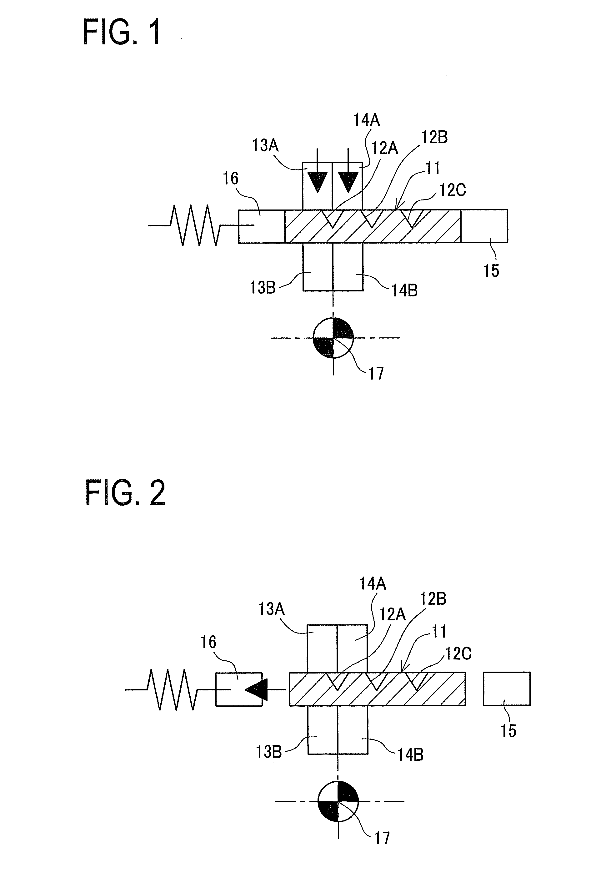
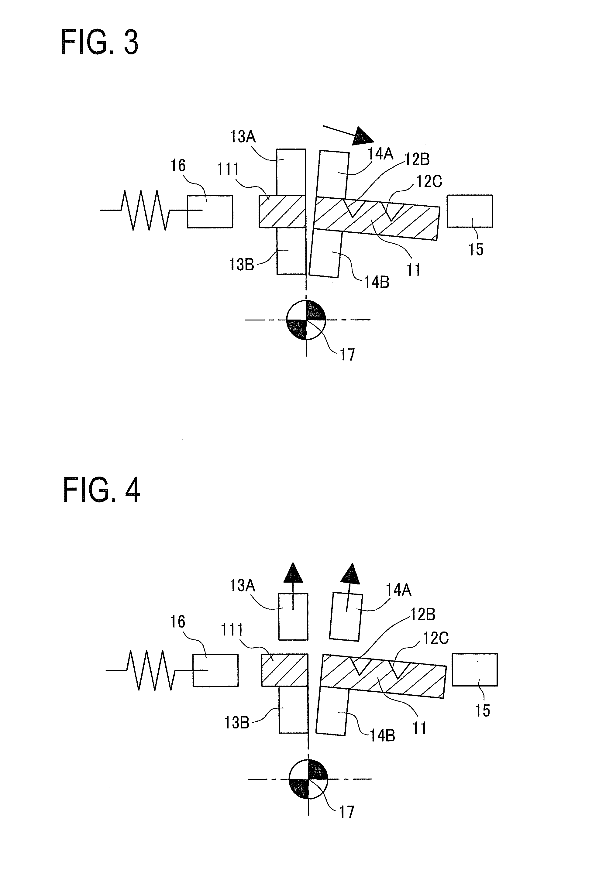
[0016]The cleavage method (the rotor manufacturing method) and the cleavage apparatus according to the invention can provide the following operations and effects. According to the above configurations (1), (6), and (7), in a cleavage method (cleavage apparatus) for cleaving a plate-shaped workpiece made of a magnetic material formed with linear recesses on a surface, the workpiece being to be cleaved along each of the linear recesses, the linear recesses are formed at two or more positions on the plate-shaped workpiece to cleave the workpiece into three or more parts, the method includes: a first positioning step of holding the plate-shaped workpiece by a positioning means in place in a direction perpendicular to the linear recesses to position a first linear recess of the linear recesses in place; a first clamping step of clamping one side of the first linear recess by a fixing clamp with a predetermined clamping force and clamping the other side by a rotating clamp with a predetermined clamping force while the plate-shaped workpiece is positioned by the positioning means; a first cleaving step of moving back the positioning means and rotationally separating the rotating clamp while maintaining the predetermined clamping force of the rotating clamp; a second positioning step of releasing the fixing clamp and the rotating clamp and causing the positioning means to position a second linear recess in place; a second clamping step of clamping one side of the second linear recess by the fixing clamp with the predetermined clamping force and clamping the other side by the rotating clamp with the predetermined force while the plate-shaped workpiece is positioned by the positioning means, and a second cleaving step of moving back the positioning means and rotationally separating the rotating clamp while maintaining the predetermined clamping force of the rotating clamp, wherein cleaved parts obtained in the first cleaving step and the second cleaving step are held with a cleaved face being abutted against a cleaved face of the plate-shaped workpiece, and the plate-shaped workpiece cleaved into three of more parts is held and carried out with their cleaved faces being abutted against each other. Accordingly, it is possible to shorten a unit time per one cleaving work including the time needed for carry-in and carry-out of a plate-shaped workpiece. Thus, a cost reduction is achieved. Accordingly, even in a carry-out work, the cleaved faces can be held as being continuously in contact with each other. This allows the cleaved faces to abut each other without rubbing, and thus prevents depression or caving-in of the surfaces of the cleaved faces and the generation of powder dust therefrom.
[0017]In the second cleaving step, the cleaved part is clamped by the fixing clamp and a remaining non-cleaved part is clamped by the rotating clamp. Thus, the cleaved part is separated from the rotating clamp. This prevents the cleaved face from rubbing against the surface of the remaining part and avoids the force generated in the second cleaving step from acting on the cleaved face. Accordingly, the surface is not depressed or caved in and no powder dust is generated therefrom.
[0018]According to the above configuration (3), in the cleavage method described in (1), a reference member of the positioning means is provided on a side of the rotating clamp and configured to push the plate-shaped workpiece unclamped by the rotating clamp toward the fixing clamp after cleavage. Accordingly, the part to be cleaved on the rotating clamp side can be precisely put in contact with the cleaved part on the fixing clamp side by being guided by the clamp plate of the rotating clamp. Specifically, when the cleaved part and the remaining plate-shaped workpiece are made contact, respective cleaved faces can be abutted against each other without rubbing against each other. This prevents depression or caving-in of the surfaces of the cleaved faces and the generation of powder therefrom.
[0019]Furthermore, when the cleaved parts are held with their cleaved faces abutting each other, an accumulated size, i.e., a total length of the cleaved parts is slightly longer than original. This may cause a problem that, when the reference member is placed on the side of the rotating clamp which is a movable side and the follower member is placed on the fixed side, the position of the linear recess can be determined precisely relative to the reference side but cannot be determined relative to the follower side. Specifically, any method other than the present invention could not precisely position the linear recess 12 in the cleavage position.
[0020]As the linear recesses are sequentially cut from the fixed side, each cleaved part is stocked on the fixed side and thus the parts can be prevented from scattering in the case of continuous high-speed cleaving. As compared with this, if the cleaved parts are stocked on the movable side, the stability of a high-speed cleaving operation may be deteriorated.
[0021]According to the above configurations (4), in the cleavage method described in (1) or (2), the plate-shaped workpiece is held and carried out, and at the same time another plate-shaped workpiece is carried in. Accordingly, even in a carry-out work, the cleaved faces can be held as being continuously in contact with each other. This allows the cleaved faces to abut each other without rubbing, and thus prevents depression or caving-in of the surfaces of the cleaved faces and the generation of powder dust therefrom.

Problems solved by technology

However, the technique of Patent Document 1 has the following problems.
Accordingly, as disclosed in Patent Document 1, in a process of forming a central linear recess in a single plate-shaped workpiece and cleaving this workpiece into two parts, it takes a long work time and also it is necessary to install a number of cleaving equipment, resulting in cost increase.
Such a long work time results from that carrying of a plate-shaped workpiece in or out of a cleavage apparatus takes long.
However, when one plate-shaped workpiece is cleaved into three or more parts, their cleaved faces may rub against each other.
Further, when a force generated in a subsequent cleaving work is applied on the cleaved faces, the cleaved face of the plate-shaped workpiece made of the fragile material is depressed or caved in, thus generating powder dust.
Therefore, it is not easy to cleave or divide a single plate-shaped workpiece into three or more parts.

Method used


Image

  • Cleavage method, rotor manufacturing method, and cleavage apparatus
  • Cleavage method, rotor manufacturing method, and cleavage apparatus
  • Cleavage method, rotor manufacturing method, and cleavage apparatus

Examples


Embodiment Construction

[0039]A detailed description of a preferred embodiment of a plate-shaped workpiece cleavage method embodying the present invention will now be given referring to the accompanying drawings. FIG. 12 is a front view of a plate-shaped workpiece cleavage apparatus and FIG. 11 is a diagram seen from an arrow A in FIG. 12.

[0040]The cleavage apparatus is configured so that a pair of central walls 21 are provided standing at a center and a rotary support shaft 22 is fixed to the central walls 21. The rotary support shaft 22 holds a fixing-clamp link 23 and a rotating-clamp link 33 as shown in FIG. 11 so that the links 23 and 33 are separately rotatable. As shown in FIG. 12, at a left end of the fixing-clamp link 23, a support shaft 25 rotatably supports a cam follower 24. At a left end of the rotating-clamp link 33, even though not appearing in the figure, at a left end of the rotating-clamp link 33, a support shaft 35 rotatably supports a cam follower 34.

[0041]On the other hand, a motor bra...


PUM

PropertyMeasurementUnit
thicknessaaaaaaaaaa
lengthaaaaaaaaaa
widthaaaaaaaaaa

Abstract

A method for cleaving a plate-shaped workpiece formed with two or more linear recesses into three or more parts includes: a first positioning step of holding the workpiece by a positioning unit in place to position a first linear recess; a first clamping step of clamping one side of the first linear recess by a fixing clamp and the other side by a rotating clamp; a first cleaving step of moving back the positioning unit and rotationally separating the rotating clamp; a second positioning step of releasing the clamps and causing the positioning unit to position a second linear recess; a second clamping step of clamping one side of the second linear recess by the fixing clamp and the other side by the rotating clamp, and a second cleaving step of moving back the positioning unit and rotationally separating the rotating clamp.

Description

CROSS-REFERENCE TO RELATED APPLICATIONS[0001]This is a national phase application based on the PCT International Patent Application No. PCT / JP2011 / 058248 filed on Mar. 31, 2011, the entire contents of which are incorporated herein by reference.TECHNICAL FIELD[0002]The present invention relates to a method for cleaving a plate-shaped workpiece or blank made of a magnetic material formed with a linear recess on its surface so that the plate-shaped workpiece is split along the linear recess.BACKGROUND ART[0003]In a motor, when a large magnet is directly mounted in a rotor, large eddy current loss is generated in the magnet by a magnetic flux. As a technique to reduce the eddy current loss, conventionally, a large magnet is cleaved or split once into a plurality of magnet parts, these cleaved magnet parts are assembled together again and mounted in a rotor. This can reduce the eddy current loss. In this case, a cleaved face is coated with resin to form a resistance layer to further redu...

Claims


Application Information

Patent Timeline
Patent Type & Authority Applications(United States)
IPC IPC(8): H02K15/02
CPCH02K15/02B26F3/002H01F41/0253H02K15/03Y10T29/49012Y10T83/051Y10T83/7487B26F3/00H01F41/02
Inventor FUBUKI, SHINGOFUKAYA, TETSUYOSHITATEBE, KATSUHIKONISHIKUMA, YASUSHI
Owner TOYOTA JIDOSHA KK
Why Eureka
Try Eureka