Heat Sink and Electronic Device and Heat Exchanger Applying the Same

Inactive Publication Date: 2014-01-16
DELTA ELECTRONICS INC
View PDF10 Cites 14 Cited by
  • Summary
  • Abstract
  • Description
  • Claims
  • Application Information

AI Technical Summary

Benefits of technology

[0028]In summary, the heat sink of the invention includes the first and second fins having the holes with different intervals. Thus, when the first and second fins are properly configured with respect to the inlet, the holes with different intervals can form a channel parallel to the airflow direction. After the air enters from the inlet, it travels through the holes with smaller intervals in advance and then through the holes with larger intervals. In other words, the air enters the heat sink and flows through the fins with higher hole density and then lower hole density in sequence. This feature can speed up the airflow passing through the fins and thus further improve the heat-dissipatio

Problems solved by technology

After the great progressive of electronic industry, the operation speed and performance of electronic elements are increased, and thus, the heat dissipation has become a very important issue for affecting the operation performance and stability.
However, the achieved heat-dissipation effect is still limited.
In other words, there still exist some heats inside the closed casing, which may damage the internal electronic element of the electronic device.
In addition, the heat sink

Method used


Image

  • Heat Sink and Electronic Device and Heat Exchanger Applying the Same
  • Heat Sink and Electronic Device and Heat Exchanger Applying the Same
  • Heat Sink and Electronic Device and Heat Exchanger Applying the Same

Examples


Embodiment Construction

[0036]The present invention will be apparent from the following detailed description, which proceeds with reference to the accompanying drawings, wherein the same references relate to the same elements.

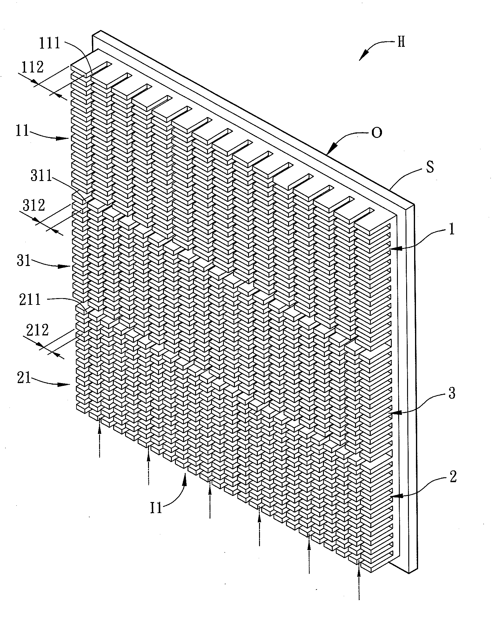
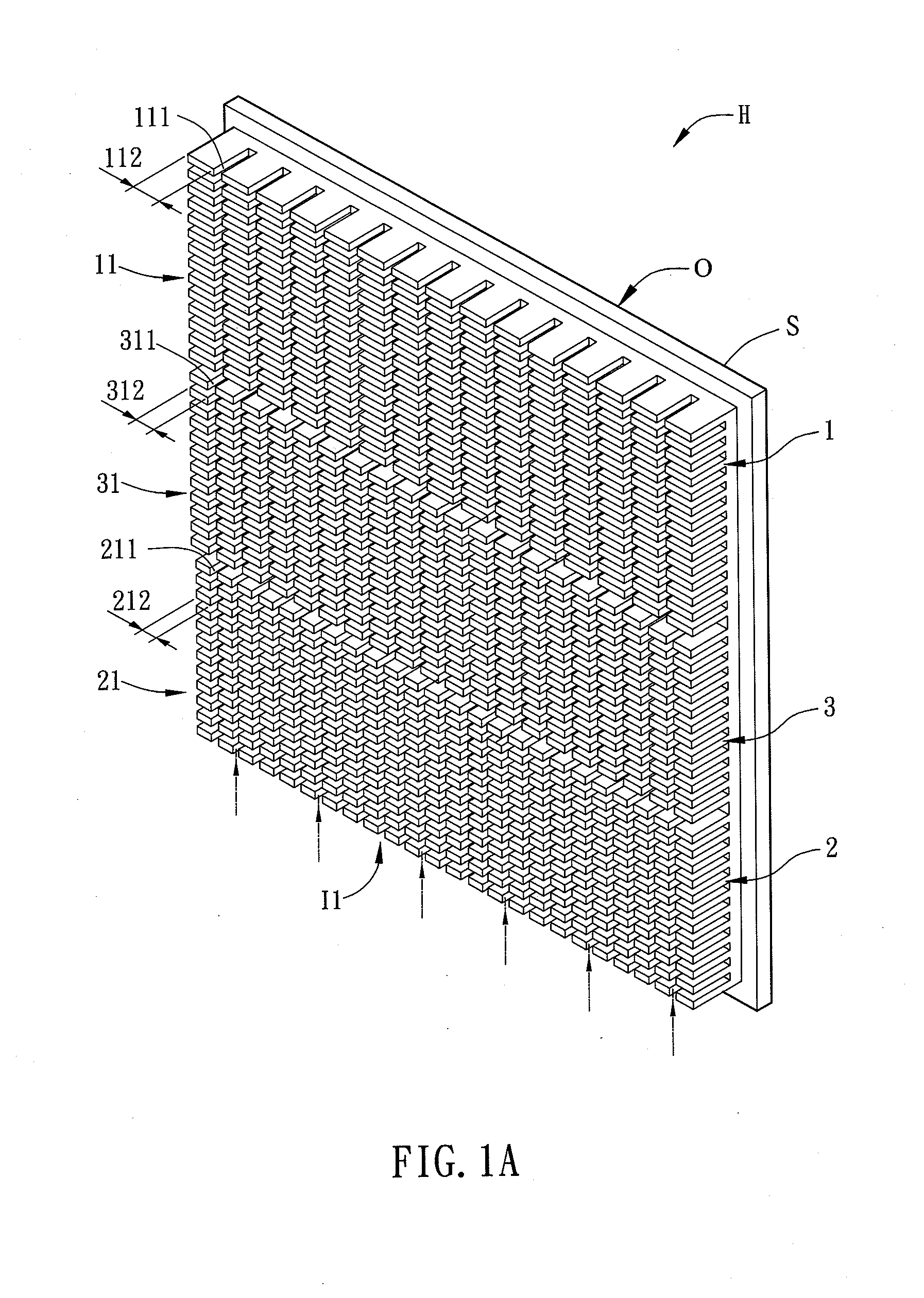
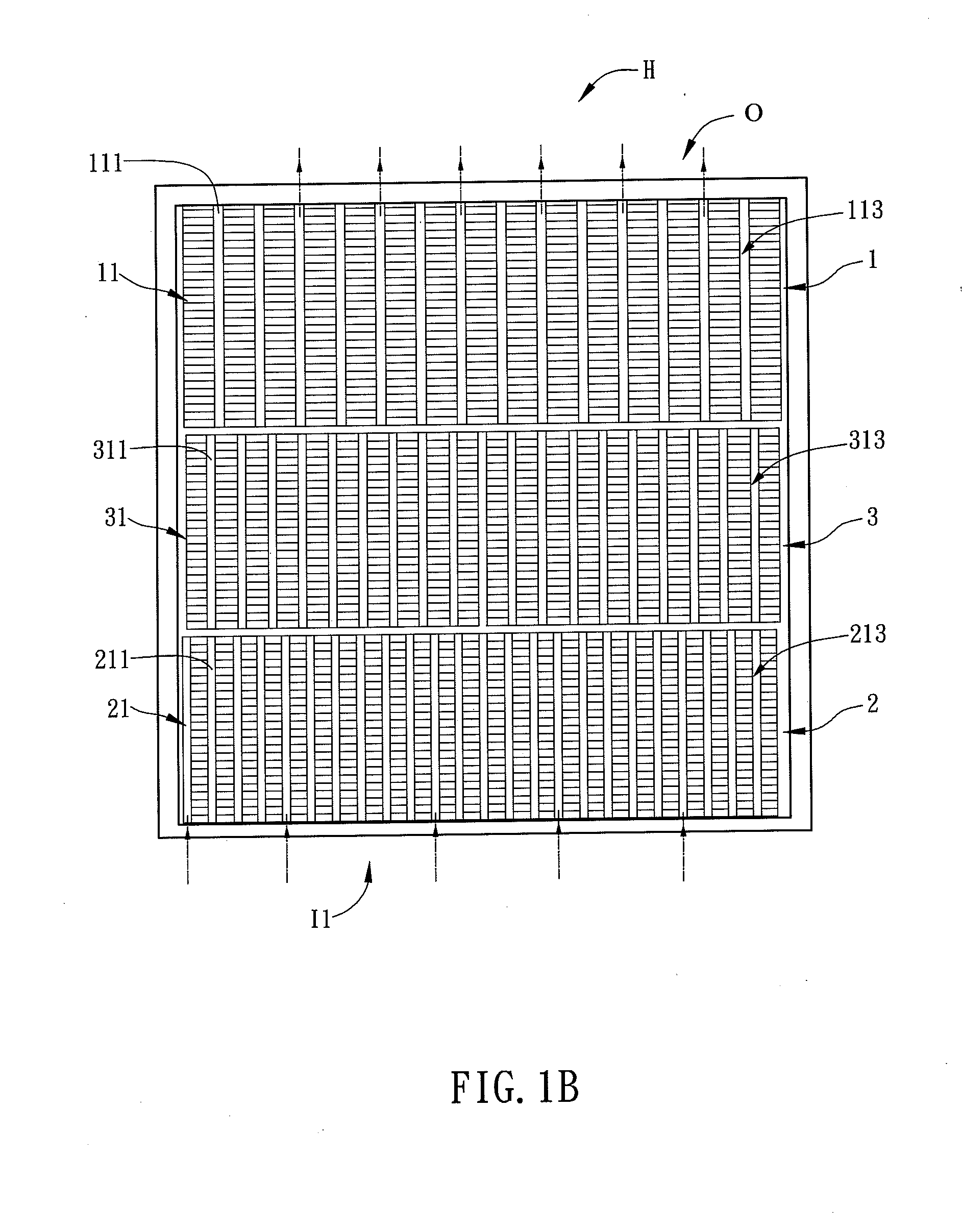
[0037]FIG. 1A is a schematic diagram showing a heat sink H according to an embodiment of the present invention, and FIG. 1B is a front view of the heat sink H of FIG. 1A. Referring to FIGS. 1A and 1B, the heat sink H includes a substrate S, at least a first fin set 1 and at least a second fin set 2. In order to achieve the desired heat dissipation, the heat sink H has a first inlet I1 and an outlet O, so that the air or gas can enter the first inlet I1, pass through the interior of the heat sink H to carry out the heat exchange, and then exit via the outlet O. The features of the structures of the heat sink H will be described hereinbelow.

[0038]The first fin set 1 and the second fin set 2 are all disposed on the substrate S. The first fin set 1 is located close to the outlet O, and at...


PUM


Abstract

A heat sink includes a substrate, at least a first fin set and at least a second fin set. The first fin set is disposed on the substrate and has a plurality of first fins, and the first fin has a plurality of first holes. The second fin set is disposed on the substrate and has a plurality of second fins, and the second fin has a plurality of second holes. The total area of the second holes is larger than that of the first holes. An electronic device and a heat exchanger which are configured with the heat sink are also disclosed. The structure and configuration of the heat fins can increase the wind guiding effect, and thus improve the heat-dissipation efficiency.

Description

CROSS REFERENCE TO RELATED APPLICATIONS[0001]This Non-provisional application claims priority under 35 U.S.C. §119(a) on Patent Application No(s). 201210243375.1 filed in People's Republic of China on Jul. 13, 2012, the entire contents of which are hereby incorporated by reference.BACKGROUND OF THE INVENTION[0002]1. Field of Invention[0003]The present invention relates to a heat sink and an electronic device and a heat exchanger using the same.[0004]2. Related Art[0005]After the great progressive of electronic industry, the operation speed and performance of electronic elements are increased, and thus, the heat dissipation has become a very important issue for affecting the operation performance and stability. In order to normally operate the electronic device, it is common to provide a heat sink on the electronic element that can generate heat, so that the generated heat can be properly dissipated through the heat sink.[0006]The conventional heat sinks for electronic devices mainly...

Claims


Application Information

Patent Timeline
IPC IPC(8): F28F3/02
CPCF28F3/02F28F2215/04H05K7/20409
Inventor WU, KUAN-LUNGCHANG, REN-CHUN
Owner DELTA ELECTRONICS INC
Why Eureka
Try Eureka