Differential mode signal transmission module

a signal transmission module and different mode technology, applied in the direction of cross-talk/noise/interference reduction, cable termination, high-frequency circuit adaptation, etc., can solve the problems of high cost of conventional flexible circuit boards and flexible circuit cables, signal transmission is also susceptible to interference, and the effect of metal shielding layer for shielding electromagnetic noise and eliminating electrostatic discharge is generally poor, so as to reduce the number of conductor wires , the effect of reducing the manufacturing cost of electronic devices and reducing the weight of electronic devices

Active Publication Date: 2014-01-16
ADVANCED FLEXIBLE CIRCUITS
View PDF12 Cites 26 Cited by
  • Summary
  • Abstract
  • Description
  • Claims
  • Application Information

AI Technical Summary

Benefits of technology

[0016]Thus, the number of conductor wires used in the extension section only needs to include the differential mode signal conductor wires so as to effectively reduce the number of conductor wires and size of the extension section thereby overcoming the difficult that extension through a bore of a hinge member or a narrow is impossible due to an excessive number of conductor wires used. Further, the manufacturing cost of electronic devices can be lowered down and the weight of the electronic devices is reduced.

Problems solved by technology

Thus, the signal transmitted is also susceptible to interference by external high frequency noises and signal distortion may result.
Although such a metal shielding layer is effective in suppress the interference caused by the external electromagnetic noises, yet the covering metal shielding layer is not actually connected the ground of an electronic device, so that the effect of the metal shielding layer for shielding electromagnetic noises and eliminating electrostatic discharge is generally poor.
However, the conventional flexible circuit boards are of costs that are much higher than the flexible circuit cables.
Further, the reason that the flexible circuit cables do not provide an effect of electromagnetic noise shielding is that the manufacture thereof is done by stretching conductor wires followed by laminating, and thus, the conductor wires cannot be made thin, which makes control of impedance difficult.
Thus, it is now an immediate challenge for the industry to reduce cost by using flexible circuit cable to partly replace the use area of the conventional flexible circuit board and to also provide a conduction structure that eliminates electrostatic discharge.
If the differential mode signal transmission terminals S are of a relatively large number, the total number of the conductor wires of the flexible circuit cable is increased and will occupy a large amount of space of a circuit in a practical application.
If the flexible circuit cable must be set through a hinge or a narrow hole, the excessive number of the conductor wires makes it difficult to smoothly extend through the bore of a hinge member or a narrow hole.
Further, the increase of the number of the conductor wires may lead to shortcomings, such as increased manufacturing cost, increased weight, and expansion of wire volume of the electronic device.

Method used


Image

  • Differential mode signal transmission module
  • Differential mode signal transmission module
  • Differential mode signal transmission module

Examples


first embodiment

[0047]Referring to FIGS. 6 and 7, FIG. 6 is a schematic view showing the present invention and FIG. 7 is a cross-sectional view taken along line 7-7 of FIG. 6. The first section 2 and the second section are each formed of a single-sided board. Taking the first section 2 as an example for explanation, the first conductive lines 23 are formed on the circuit board 211. The upper surface of the first conductive lines 23 is covered with an insulation layer 24, the insulation layer 24 forms a holed structure H1 at a location corresponding to the first conductive line 23 connected to the grounding terminal G21, forms a holed structure H2 at a location corresponding to the first conductive line 23 connected to the grounding terminal G22, and also forms a holed structure H3 at a location corresponding to the first conductive line 23 connected to the grounding terminals G23.

[0048]In the first embodiment of the present invention, besides the collective grounding line terminal G2, the first dif...

third embodiment

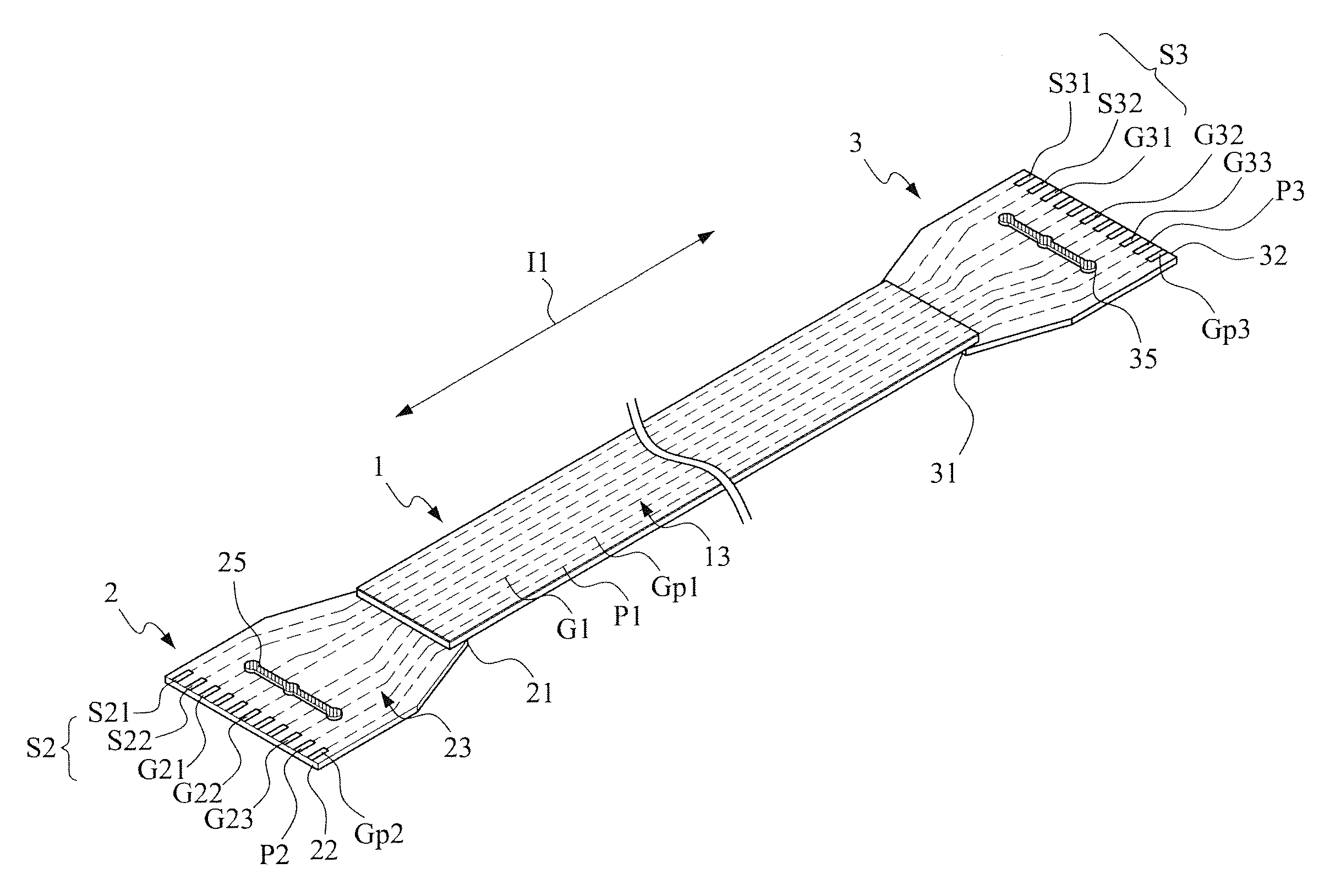
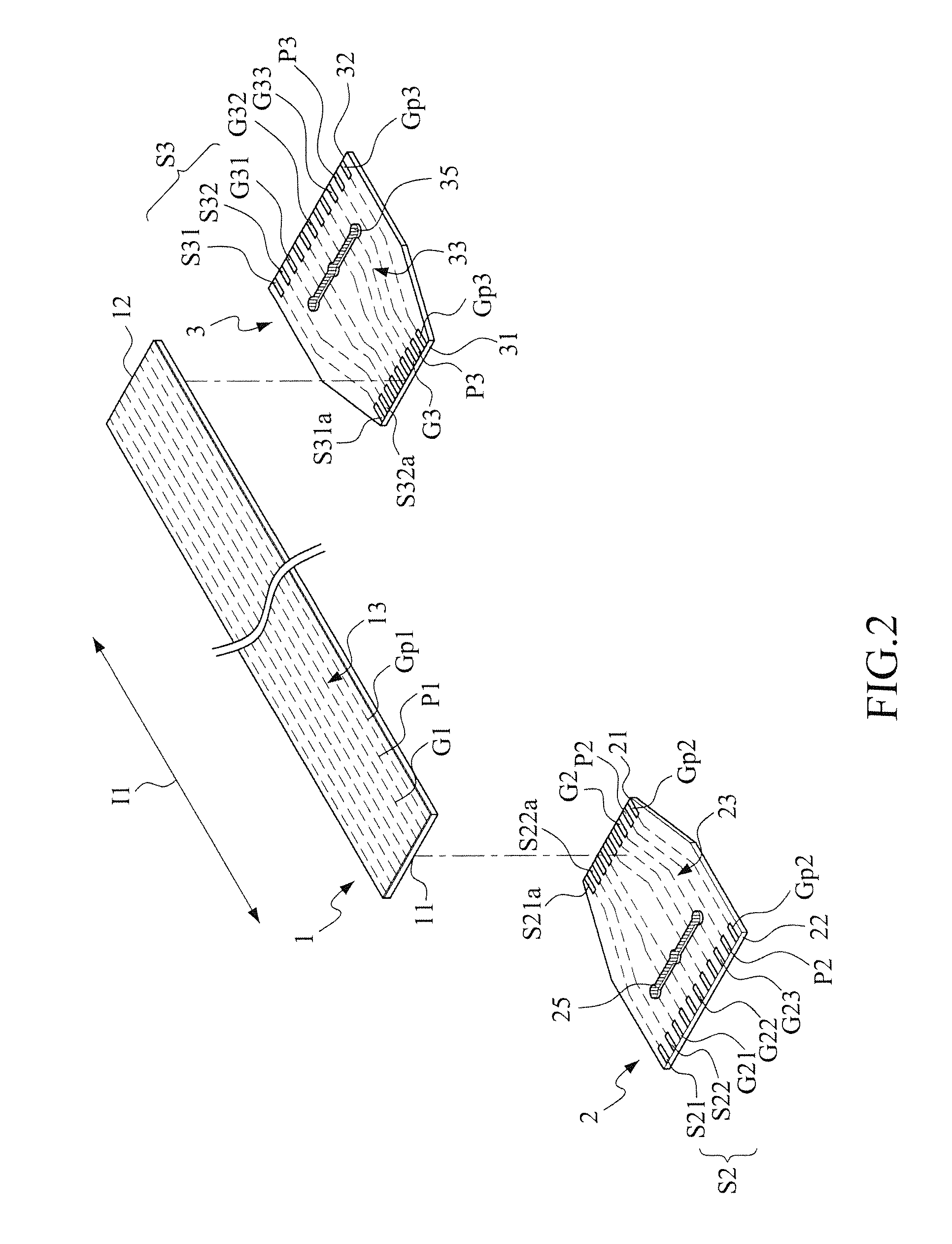
[0053]In the embodiment shown in FIG. 2, the plurality of conductor wires 13 of the extension section 1 comprise the grounding line G1; the extension connection end 21 of the first section 2 comprises the collective grounding point G2; and the extension connection end 31 of the second section 3 comprises the collective grounding point G3. However, in the present invention (see FIG. 11), arrangements may be made such that the plurality of conductor wires 13 of the extension section 1 comprises no grounding line G1, the extension connection end 21 of the first section 2 comprises no collective grounding point G2, and the extension connection end 31 of the second section 3 comprises no collective grounding point G3, while each of the grounding terminals G21, G22, G23 of the first section 2 is connected by the first conductive connection line 25 to any collective grounding point of an electronic device or can be grounded via the primary grounding terminal Gp2. Similarly, each of the gro...

fourth embodiment

[0054]The extension connection end 21 of the first section 2 can be connected by soldering to the first end 11 of the extension section 1 and the extension connection end 31 of the second section 3 can also be connected by soldering to the second end 12 of the extension section 1. It is apparent that the connection can be done with other suitable means. For example, in the present invention shown in FIG. 12, the extension connection end 21 of the first section 2 and the first end 11 of the extension section 1 are connectable to each other through insertion into a connector 181. The extension connection end 31 of the second section 3 and the second end 12 of the extension section 1 are also connectable to each other through insertion into another connector 182.


PUM


Abstract

A differential mode signal transmission module includes a first section having an external connection end on which at least a pair of differential mode signal transmission terminals are formed and includes a grounding terminal, a first differential mode signal terminal, and a second differential mode signal terminal. The extension connection end of the first section forms a counterpart signal terminals corresponding to those of the external connection end. At least one first conductive connection line is formed on the first section. The conductive connection line connects the grounding terminal of the external connection end of the first section to a collective grounding point. The extension connection end of the first section is connected to an extension section. The extension section is further connected to a second section opposite to the first section. The extension section includes at least one slit line in order to form a bundled section. The first section, the second section, and the extension section include at least one fold line.

Description

BACKGROUND OF THE INVENTION[0001]1. Field of the Invention[0002]The present invention relates to a signal transmission circuit cable, and in particular to a differential mode signal transmission module for transmitting differential mode signals.[0003]2. The Related Arts[0004]General processes for manufacturing flexible circuit boards can be classified as (1) a flexible board formed by transferring image to and etching a conductor layer and laminating an insulation layer, (2) a flexible board formed by directly printing a conductor layer on an insulation substrate, and (3) a standard flexible circuit cable formed by stretching a plurality of straight and parallel conductor wires by a coiling machine and laminating an insulation layer. Classification made according to functionality may include carrier boards, flat cables, and flexible printed circuit board featuring functions of both carrier board and flat cable. The flexible circuit boards bear numerous different names, such as flexi...

Claims


Application Information

Patent Timeline
Patent Type & Authority Applications(United States)
IPC IPC(8): H02G15/08
CPCH02G15/08H05K1/0219H05K1/0225H05K1/0245H05K1/0253H05K1/117H05K1/118H05K1/147H05K2201/0715H05K2201/09063H05K2201/09254
Inventor LIN, GWUN-JINSU, KUO-FU
Owner ADVANCED FLEXIBLE CIRCUITS
Why Eureka
Try Eureka