
Circuit for driving gate of power mos transistor

a technology of power mos transistor and gate, which is applied in the direction of logic circuit coupling/interface arrangement, pulse technique, instruments, etc., can solve the problems of interference with wireless data communication, high electromagnetic interference (emi) noise, etc., and achieve the effect of suppressing emi and preventing malfunction

Active Publication Date: 2014-01-16
SAMSUNG ELECTRONICS CO LTD
View PDF8 Cites 23 Cited by
  • Summary
  • Abstract
  • Description
  • Claims
  • Application Information

AI Technical Summary

Benefits of technology

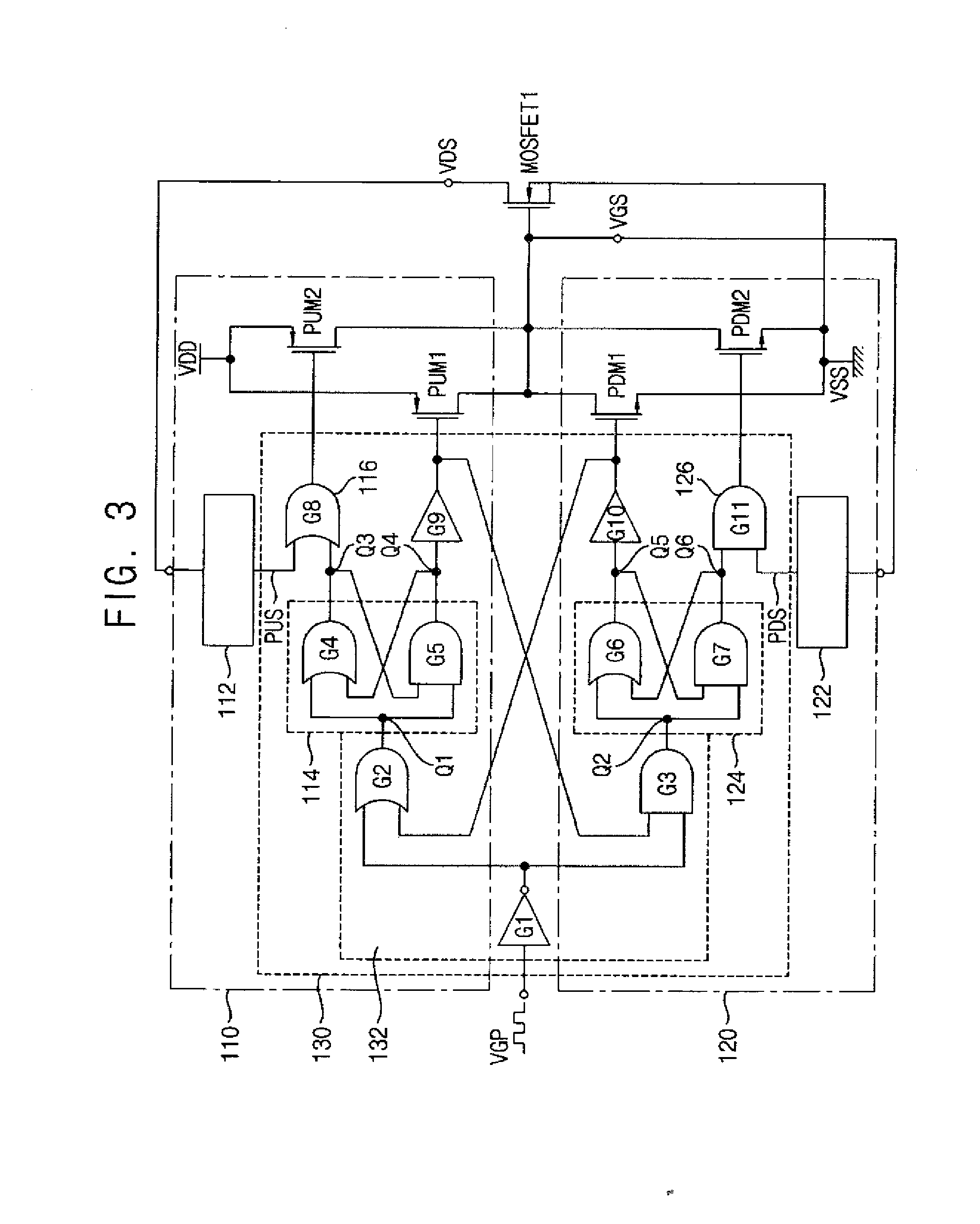
The invention provides a circuit for driving a power MOS transistor that reduces EMI noise by controlling the switching speed of the power switching transistor based on its transition state. The circuit includes an adaptive pull-up unit and an adaptive pull-down unit that maximize their driving ability during the falling and rising transitions of the power MOS transistor, respectively. This allows the circuit to adaptively control the slopes in the transitions and suppress EMI noise during turn-off. The technical effect is to reduce malfunctions caused by EMI noise and minimize switching loss during the transitions of the power MOS transistor.

Problems solved by technology

However, when the switching frequency is increased, a higher Electromagnetic Interference (EMI) noise is generated, which interferes with wireless data communication.

Method used


Image

  • Circuit for driving gate of power mos transistor
  • Circuit for driving gate of power mos transistor
  • Circuit for driving gate of power mos transistor

Examples


Embodiment Construction

[0040]The inventive concept will be described more fully with reference to the accompanying drawings, in which exemplary embodiments thereof are shown. This inventive concept may, however, be embodied in many different forms and should not be construed as limited to the embodiments set forth herein. Like reference numerals refer to like elements throughout this application.

[0041]It will be understood that when an element is referred to as being “connected” or “coupled” to another element, it can be directly connected or coupled to the other element or intervening elements may be present. As used herein, the singular forms “a,”“an” and “the” are intended to include the plural forms as well, unless the context clearly indicates otherwise.

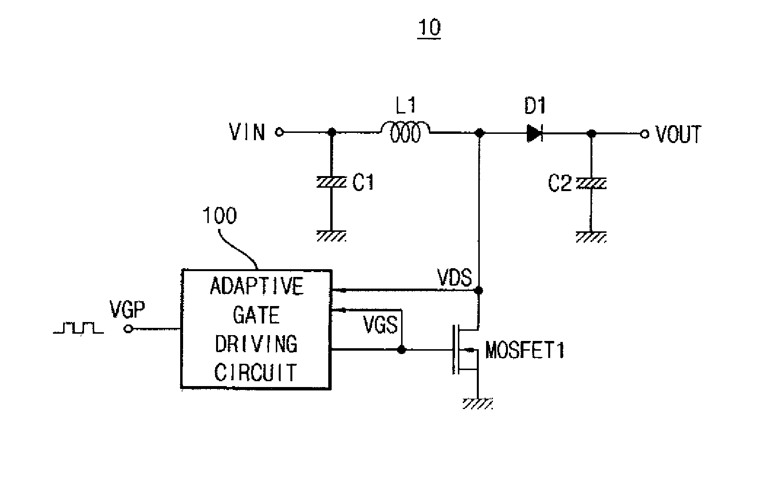
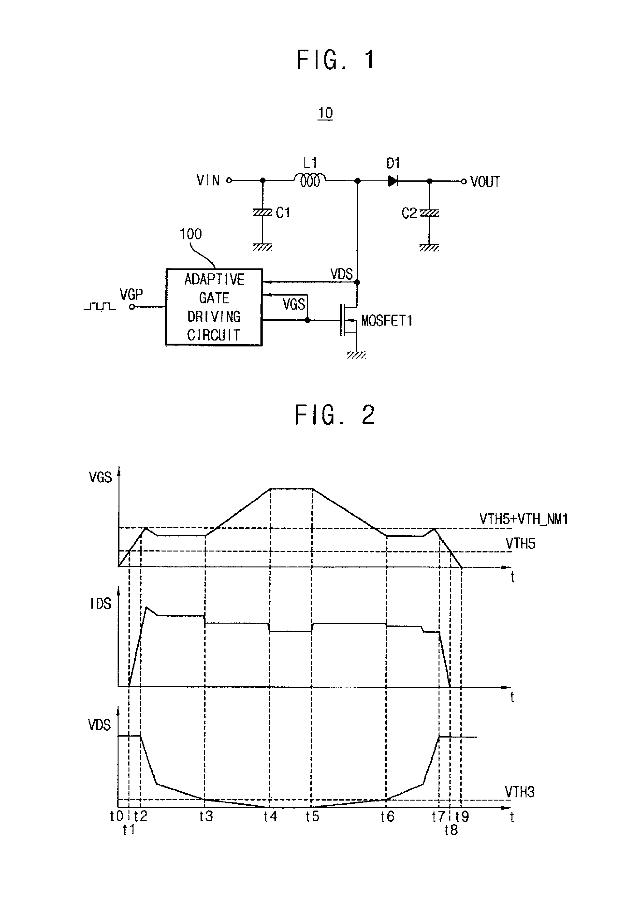
[0042]FIG. 1 is a circuit diagram showing a DC-DC converter according to an exemplary embodiment of the inventive concept.

[0043]In the DC-DC converter 10, an inductor L1 is charged by an input direct current voltage Vin when a power MOS transistor MOS...


PUM


Abstract

A circuit for driving a gate of a power MOS transistor includes an adaptive pull-up unit and an adaptive pull-down unit. The adaptive pull-up unit is connected between a first power source voltage and the gate of the power MOS transistor. The adaptive pull-up unit maximizes pull-up current driving ability. The adaptive pull-down unit is connected between a second power source voltage and the gate of the power MOS transistor. The adaptive pull-down unit maximizes pull-down current driving ability.

Description

CROSS-REFERENCE TO RELATED APPLICATION[0001]This application claims priority under 35 USC §119 to Korean Patent Application No. 10-2012-0074931, filed on Jul. 10, 2012 in the Korean Intellectual Property Office (KIPO), the disclosure of which is incorporated by reference in its entirety herein.BACKGROUND[0002]1. Technical Field[0003]Example embodiments of the inventive concept relate generally to driving circuits, and more particularly to a circuit for driving a gate of a power MOS transistor.[0004]2. Discussion of Related Art[0005]Devices that perform wireless data communication, such as a laptop computer, a mobile phone or a tablet PC, may include a DC-DC converter and a Power Management Integrated Circuit (PMIC). A DC-DC converter is an electronic circuit which converts a source of direct current from one voltage level to another voltage level. A PMIC is an integrated circuit for managing power requirements. A switching frequency of the DC-DC converter applied to the PMIC may be ...

Claims


Application Information

Patent Timeline
Patent Type & Authority Applications(United States)
IPC IPC(8): H02M3/158H03K19/0175
CPCH03K19/017509H02M3/158H02M3/155H03K17/94
Inventor YOUN, HYO-SANGKIM, WOO-SEOK
Owner SAMSUNG ELECTRONICS CO LTD
Learn More