
Power gating circuit

Active Publication Date: 2014-01-16
SAMSUNG ELECTRONICS CO LTD
View PDF13 Cites 27 Cited by
  • Summary
  • Abstract
  • Description
  • Claims
  • Application Information

AI Technical Summary

Benefits of technology

The invention is a power gating circuit that has several advantages. It can provide a longer time delay with a smaller circuit size. It can also minimize power consumption when in active mode. Additionally, it can reduce the deviation in time delay caused by changes in process, voltage, and temperature.

Problems solved by technology

Electronic products consume an ever increasing amount of power since they are being equipped with an increasing number of high-performance functions.
However, the time delay circuit may take up a large area of the page gating circuit.
In addition, since a time delay generated by the time delay circuit may vary depending on a variation of process, voltage and temperature (PVT), current may not be effectively controlled.

Method used


Image

  • Power gating circuit
  • Power gating circuit
  • Power gating circuit

Examples


Embodiment Construction

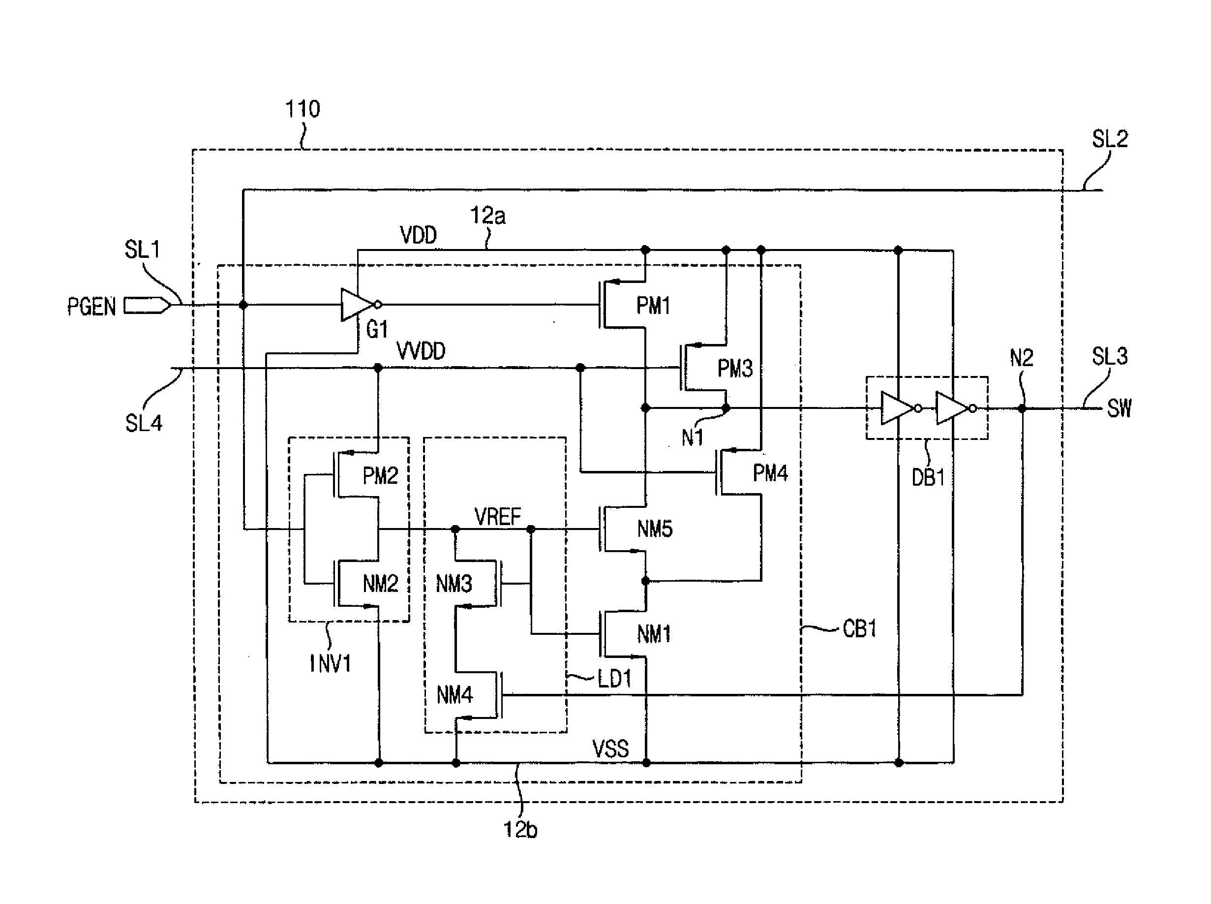
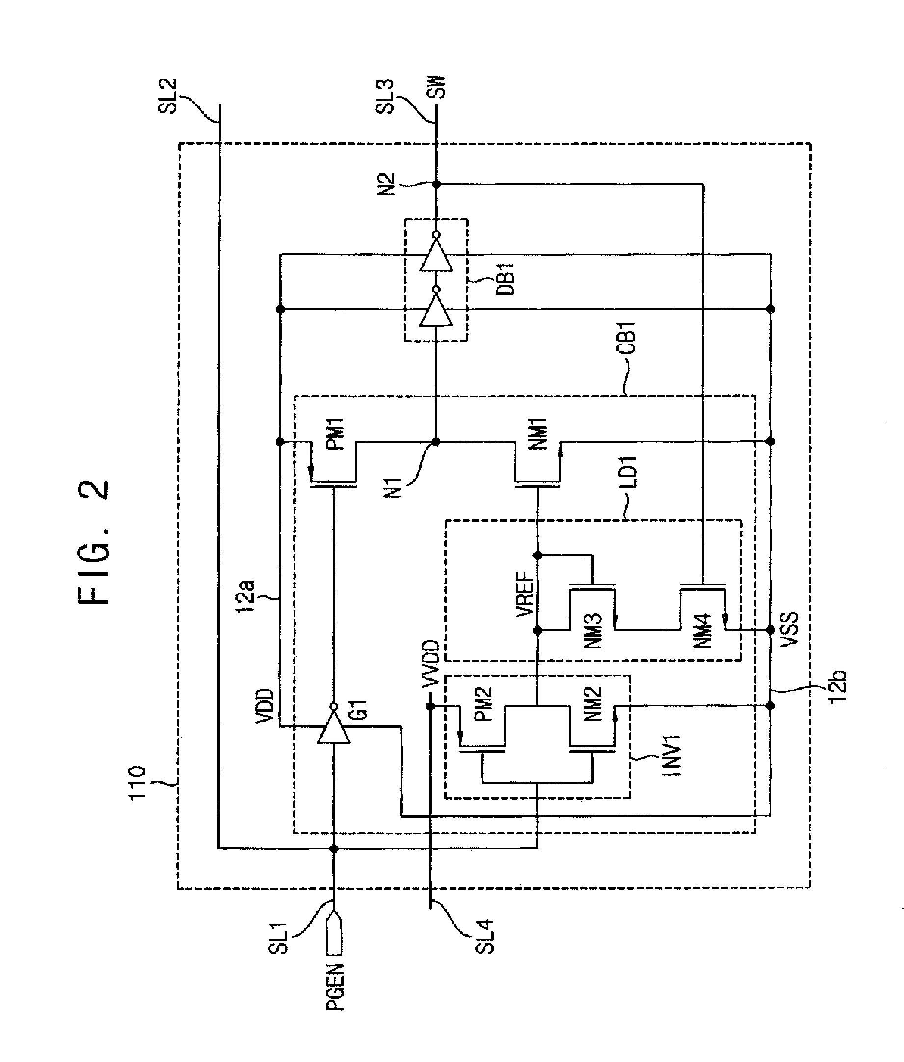
[0045]The inventive concept will be described more fully with reference to the accompanying drawings, in which some exemplary embodiments thereof are shown. The present inventive concept may, however, be embodied in many different forms and should not be construed as limited to the embodiments set forth herein. Like reference numerals refer to like elements throughout this application.

[0046]It will be understood that when an element is referred to as being “connected” or “coupled” to another element, it can be directly connected or coupled to the other element or intervening elements may be present. As used herein, the singular forms “a,”“an” and “the” are intended to include the plural forms as well, unless the context clearly indicates otherwise.

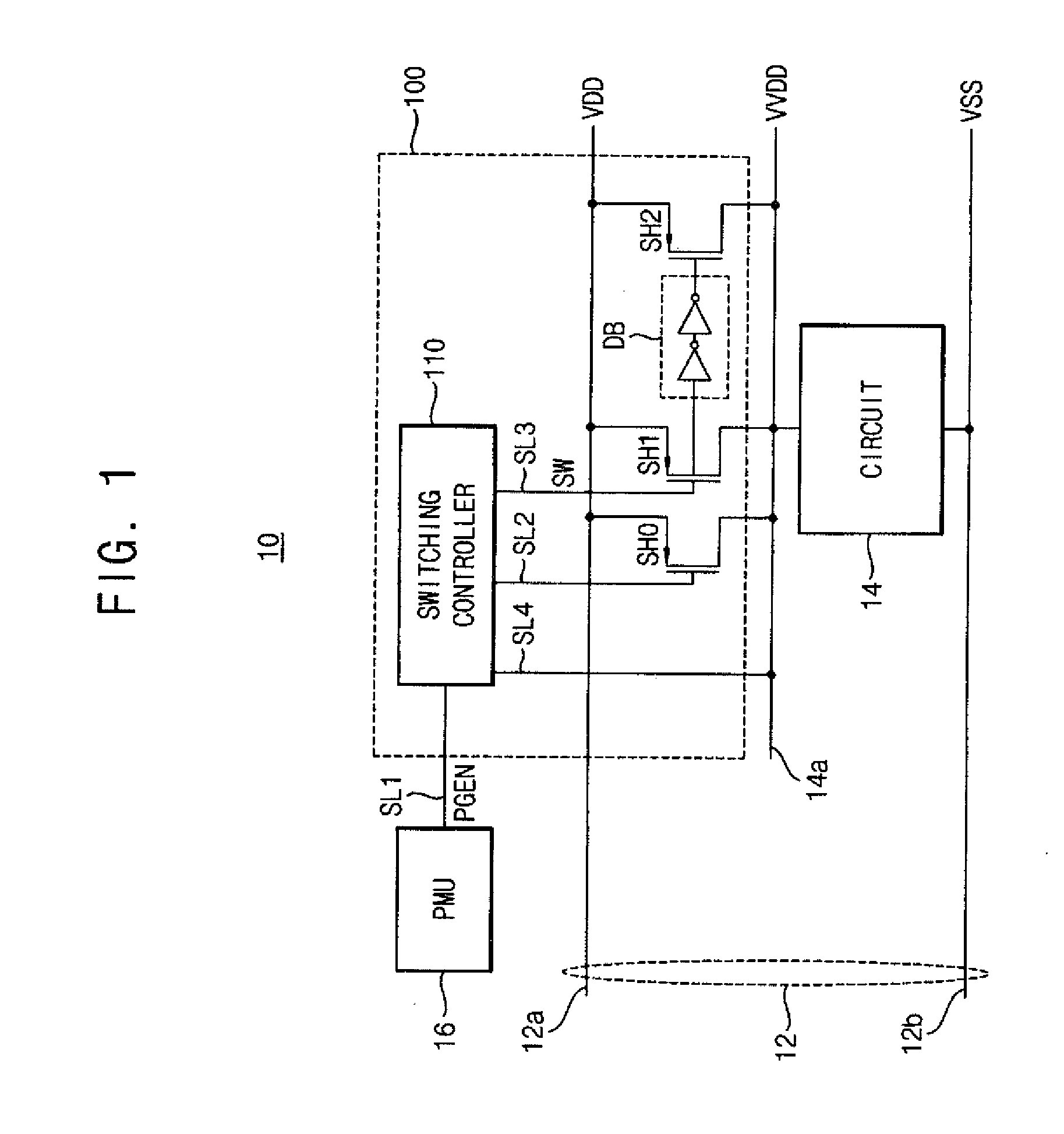
[0047]FIG. 1 is a block diagram illustrating a header-type power gating circuit of an integrated circuit apparatus according to an exemplary embodiment of the inventive concept.

[0048]Referring to FIG. 1, a power rail 12 connected to an ext...


PUM


Abstract

A power gating circuit includes a first current switch, a second current switch, and a switching controller. The first current switch is connected between a power rail and a circuit block operated by an operating supply voltage, and provides a first current when turned on. The second current switch is connected between the power rail and circuit block, and provides a second current larger than the first current when turned on. The switching controller turns on first current switch when transitioned from a sleep mode to an active mode to change the operating supply voltage using the first current, generates a reference voltage based on the operating supply voltage that changes more slowly than the operating supply voltage, and turns on the second current switch based on the reference voltage to provide the second current to the circuit block.

Description

CROSS-REFERENCE TO RELATED APPLICATION[0001]This application claims priority under 35 USC §119 to Korean Patent Application No. 10-2012-0074996, filed on Jul. 10, 2012, in the Korean Intellectual Property Office (KIPO), the disclosure of which is incorporated by reference in its entirety herein.BACKGROUND[0002]1. Technical Field[0003]Exemplary embodiments of the inventive concept relate generally to a power gating circuit of an integrated circuit apparatus, and more particularly to a power gating circuit of a System on Chip (SoC).[0004]2. Discussion of Related Art[0005]Electronic products consume an ever increasing amount of power since they are being equipped with an increasing number of high-performance functions. When these electronic products are mobile devices, they require a battery to supply this power. A System on Chip (SoC) may be employed in an electronic device along with power management software to reduce the amount of power consumed.[0006]A power gating circuit may be ...

Claims


Application Information

Patent Timeline
IPC IPC(8): H03K17/14
CPCH03K17/145H03K19/0016G05F3/02G05F5/00
Inventor YOON, JANG-HWANKIM, JIN-SUNGBAECK, SANG-YEOP
Owner SAMSUNG ELECTRONICS CO LTD
Learn More