
Millimeter-Wave Band Radio Transceiver Device

Active Publication Date: 2014-01-16
TOKYO INST OF TECH
View PDF4 Cites 21 Cited by
  • Summary
  • Abstract
  • Description
  • Claims
  • Application Information

AI Technical Summary

Benefits of technology

The patent text describes a new technology that allows for better control over the movement of objects. This can be useful in various applications such as manufacturing, logistical systems, and even sports equipment. The key technical effect is the development of a more precise and flexible control system for moving objects.

Problems solved by technology

Therefore, improving phase noise of the local oscillator is a challenge in realizing a millimeter-wave band radio communication device.
It is technically difficult to realize any of the above structures because of problems such as I / Q mismatching.

Method used


Image

  • Millimeter-Wave Band Radio Transceiver Device
  • Millimeter-Wave Band Radio Transceiver Device
  • Millimeter-Wave Band Radio Transceiver Device

Examples


Embodiment Construction

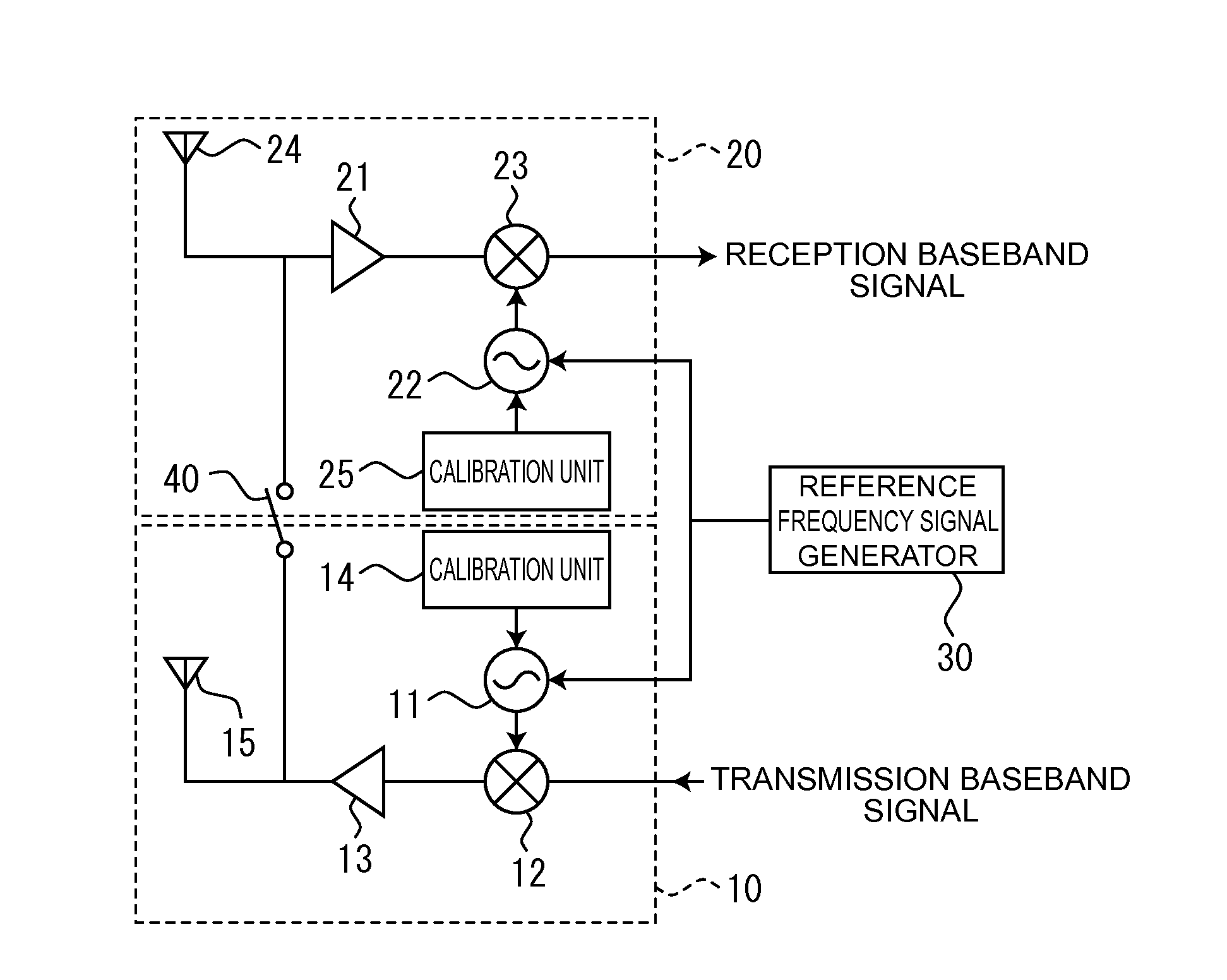
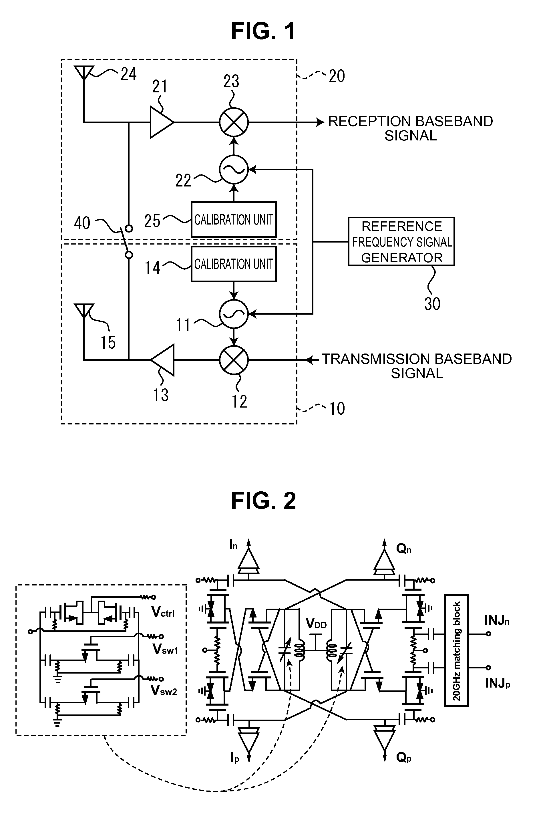
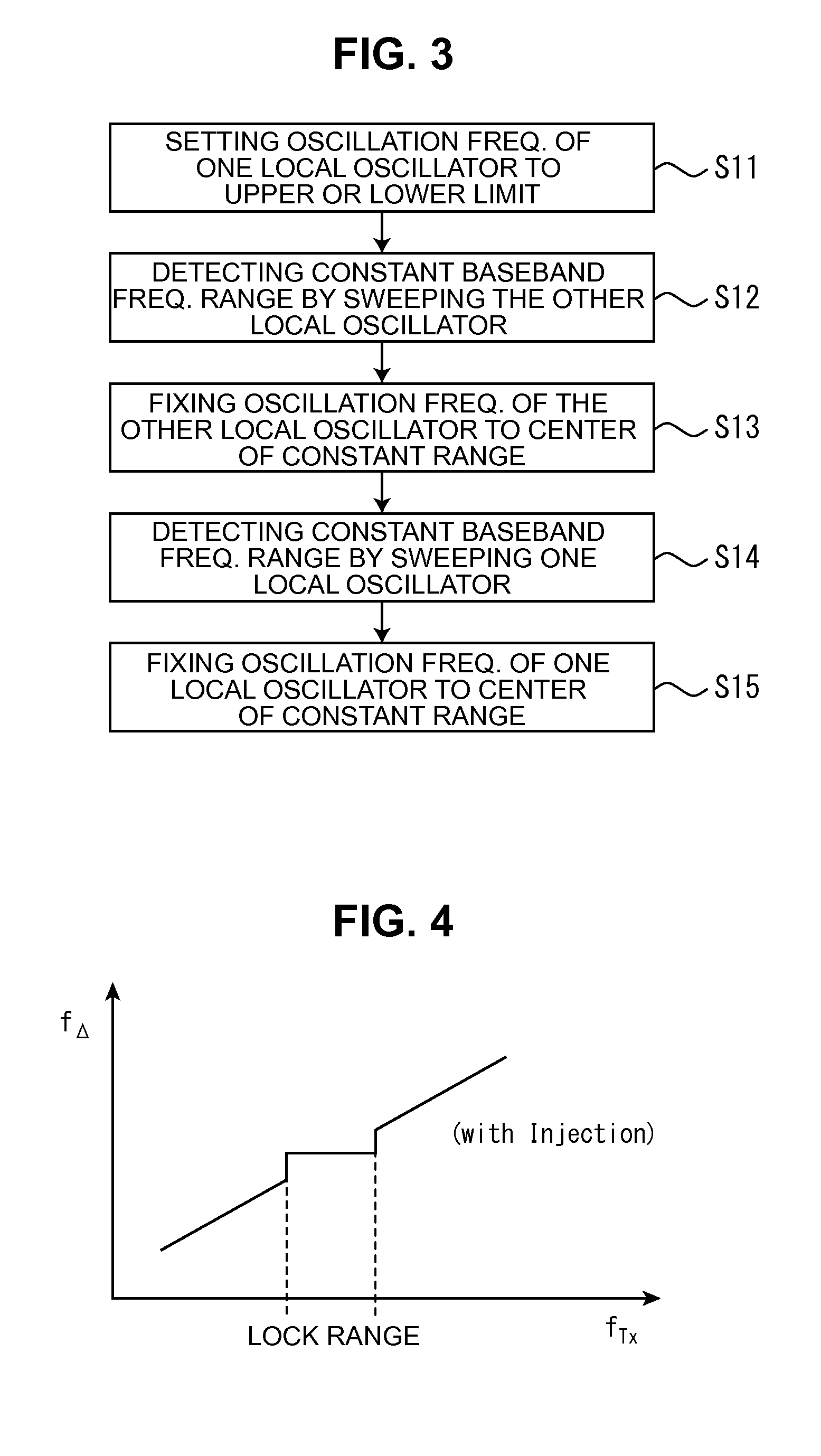
[0023]Preferred embodiments of the present invention will be described below with reference to the accompanying drawings. FIG. 1 is a schematic plane view of a millimeter-wave band radio transceiver device of the present invention. As shown in the drawing, the millimeter-wave band radio transceiver device of the present invention mainly includes a transmitter unit 10, a receiver unit 20, and a reference frequency signal generator 30. A reference frequency signal generated by the reference frequency signal generator 30 is injected into a local oscillator for upconversion 11 of the transmitter unit 10 and a local oscillator for downconversion 22 of the receiver unit 20, which are described later. Incidentally, for the transmitter unit 10 and the receiver unit 20, the same circuit configuration basically may be used. In the following description, the transmitter unit 10 will be basically detailed; regarding the receiver unit 20, differences from the transmitter unit 10 will be primaril...


PUM


Abstract

Provided is a millimeter wavelength range transceiver device which can improve phase noise characteristics and which can also independently calibrate each respective local oscillator of a transmission unit and a reception unit. This millimeter wavelength range transceiver device comprises a transmission unit (10), a reception unit (20), and a reference frequency signal generator (30). The transmission unit (10) comprises a transmission-use local oscillator (11) comprising an injection-locked oscillator, a transmission-use mixer (12) for mixing the signal from the transmission-use local oscillator and a transmission baseband signal, and a transmission-use amplifier (13) for amplifying the signal from the transmission-use mixer to a transmission-use antenna (15). The reception unit (20) comprises a reception-use amplifier (25) for amplifying a signal from a reception-use antenna (24), a reception-use local oscillator (22) comprising an injection-locked oscillator, and a reception-use mixer (23) for mixing the signal from the reception-use local oscillator and the signal from the reception-use amplifier in order to output a reception baseband signal. A reference frequency signal generator (30) injects a reference frequency signal into the transmission-and-reception-use local oscillators (11 and 22).

Description

TECHNICAL FIELD[0001]The present invention relates to a millimeter-wave band radio transceiver device, and more particularly to a millimeter-wave band radio transceiver device that uses an injection-locked oscillator.BACKGROUND ART[0002]Currently, there is increasing demand for use of radio transceiver devices in mobile communications and the like; Improvements in communication quality and reliability are desired more than ever. As for radio transceiver devices of a millimeter-wave band (e.g. 60 GHz band), in order to simplify circuit configurations and reduce costs, what is proposed is a radio transceiver device of a direct conversion type that is designed to downconvert or upconvert the 60 GHz directly to a baseband. In general, such a radio transceiver device includes an amplifier, which amplifies a high-frequency signal, a mixer circuit, and a local oscillator. Among the above components, a signal from the local oscillator that generates a carrier signal influences the character...

Claims


Application Information

Patent Timeline
IPC IPC(8): H04L25/08
CPCH04L25/08H03L7/24H04B1/40H03B5/1228H03B5/1212H03B27/00H03B5/1253
Inventor OKADA, KENICHIMATSUZAWA, AKIRA
Owner TOKYO INST OF TECH
Learn More