High frequency distributed oscillator using coupled transmission line

a transmission line and high frequency technology, applied in oscillator generators, semiconductor/solid-state device details, semiconductor devices, etc., can solve the problems of difficult design of oscillators, low frequency tuning characteristic, and generation of parasitic components or parasitic parameters, so as to improve phase noise characteristics and increase frequency selectivity

Inactive Publication Date: 2006-02-23
KOREA ADVANCED INST OF SCI & TECH
View PDF1 Cites 6 Cited by
  • Summary
  • Abstract
  • Description
  • Claims
  • Application Information

AI Technical Summary

Benefits of technology

[0020] Accordingly, the present invention has been made in view of the above problems occurring in the prior art, and it is an object of the present invention to provide a distributed oscillator in which coupled transmission lines, which can increase the frequency selectivity, are used as transmission lines, wherein signal interference occurs among the coupled transmission lines because of mutual approximation, and the coupled transmission lines serve as a filter at a predetermined frequency due to the signal interference, whereby a phase noise characteristic can be improved.

Problems solved by technology

In a several GHz bandwidth, however, if a circuit in which an application frequency operates 10 GHz or more is used although not becoming a significant problem in analyzing the circuit, parasitic component or parasitic parameters are generated in the inductor and the capacitor.
An oscillator is difficult to design so that it operates at a desired frequency and a frequency tuning characteristic is also significantly lowered, because of the parasitic component or parasitic parameters.
There is a disadvantage in that it is difficult to design and implement a passive element due to the parasitic parameters.
However, the distributed oscillator is disadvantageous in that the chip size increases because a ground line has to be formed at both sides of a signal line when designing the distributed oscillator.

Method used


Image

  • High frequency distributed oscillator using coupled transmission line
  • High frequency distributed oscillator using coupled transmission line
  • High frequency distributed oscillator using coupled transmission line

Examples


Embodiment Construction

[0033] The present invention will now be described in detail in connection with preferred embodiments with reference to the accompanying drawings.

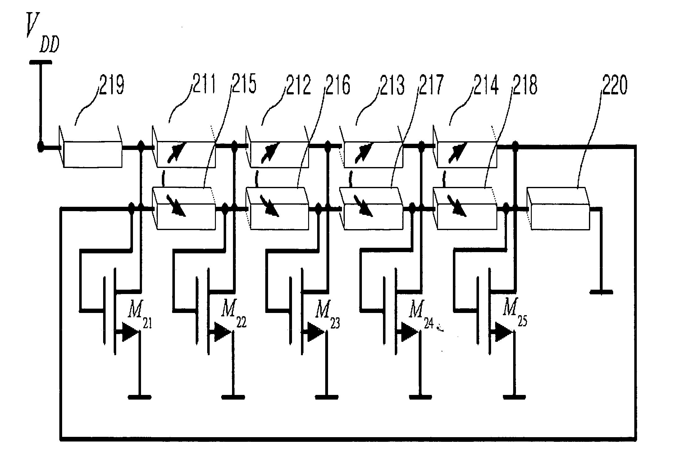
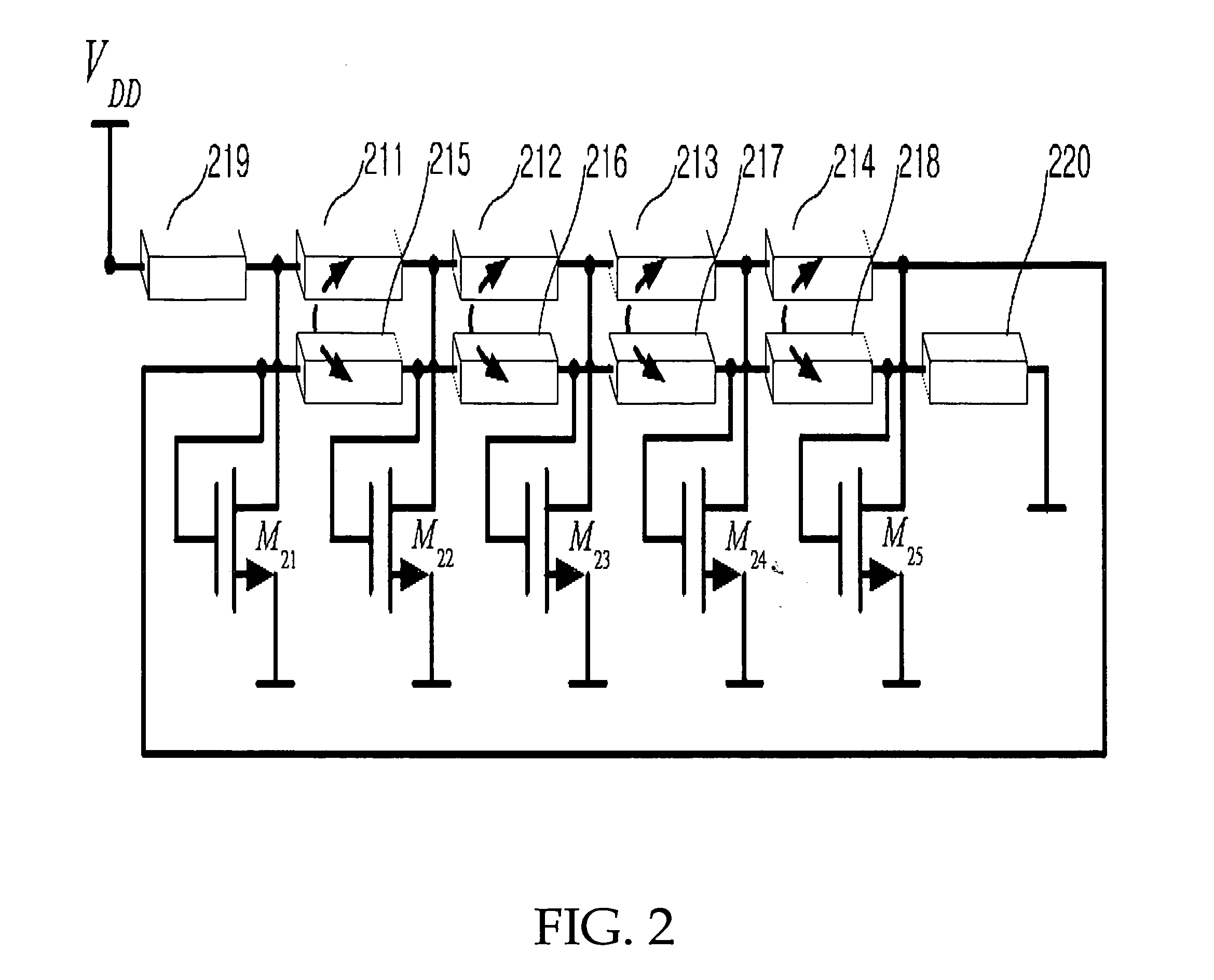
[0034]FIG. 2 is a circuit diagram illustrating the operational principle of a coupled type distributed oscillator according to the present invention.

[0035] The construction and operation of the coupled type distributed oscillator will not be described with reference to FIG. 2.

[0036] Referring to FIG. 2, the coupled type distributed oscillator includes active elements M21 to M25 respectively having first to third terminals, which are responsible for signal amplification, and coupled transmission lines 211 to 220.

[0037] In this time, the coupled type distributed oscillator according to the present invention employs the coupled transmission lines 211 to 220 so as to increase the frequency selectivity.

[0038] Furthermore, the coupled transmission lines 215, 216, 217 and 218 are connected to the input terminals of the active elements M21 to...


PUM


Abstract

The present invention relates to a distributed oscillator, and more particularly, to a high frequency distributed oscillator using coupled transmission lines. According to the present invention, coupled transmission lines capable of increasing the frequency selectivity are used as transmission lines. Signal interference occurs among the coupled transmission lines because of mutual approximation. The coupled transmission lines serve as a filter due to the signal interference. A phase noise characteristic can be thus increased.

Description

BACKGROUND OF THE INVENTION [0001] 1. Field of the Invention [0002] The present invention relates to a distributed oscillator, and more particularly, to a high frequency distributed oscillator using coupled transmission lines. [0003] 2. Background of the Related Art [0004] In an oscillation circuit, an oscillator using an inductor and a capacitor as a resonator has been widely used. [0005] In a several GHz bandwidth, however, if a circuit in which an application frequency operates 10 GHz or more is used although not becoming a significant problem in analyzing the circuit, parasitic component or parasitic parameters are generated in the inductor and the capacitor. [0006] That is, capacitance of the capacitor exists in the conductor of the inductor, and inductance component also exists in the plate of the capacitor. [0007] An oscillator is difficult to design so that it operates at a desired frequency and a frequency tuning characteristic is also significantly lowered, because of the ...

Claims


Application Information

Patent Timeline
Patent Type & Authority Applications(United States)
IPC IPC(8): H03B5/18
CPCH03B5/20H03B5/1841H03B5/12
Inventor YOON, EUISIKPARK, EUN-CHUL
Owner KOREA ADVANCED INST OF SCI & TECH
Why Eureka
Try Eureka