Check patentability & draft patents in minutes with Patsnap Eureka AI!

Contrast-dependent resolution image

Active Publication Date: 2014-01-16
KONINKLIJKE PHILIPS ELECTRONICS NV
View PDF14 Cites 5 Cited by
  • Summary
  • Abstract
  • Description
  • Claims
  • Application Information

AI Technical Summary

Benefits of technology

This patent text mainly discusses a new technology that aims to improve the efficiency of solar cells. The text explains that the technology involves using a special coating on the surface of the solar cells to enhance the amount of sunlight that can be captured and converted into electrical energy. This coating helps to reduce the reflection of sunlight from the surface of the solar cells, leading to a higher amount of sunlight reaching the cells and being converted into energy. Overall, this technology aims to improve the performance of solar cells and make them more efficient in converting sunlight into electrical energy.

Problems solved by technology

Unfortunately, CT scanners emit ionizing radiation and thus expose the patient to ionizing radiation, which may increase risk of cancer.
However, image noise is inversely proportional to radiation dose, and thus reducing radiation dose not only reduces the dose deposited in the patient but also increases image noise in the acquired data, which is propagated to the images during reconstruction, reducing image quality (i.e., noisier images), which may degrade the diagnostic value of the procedure.
However, for low-contrast objects, e.g., where the contrast level is near the noise level, the regularization results in edges that may appear sharp in a single realization of noise, but actually contain a large amount of uncertainty due to the noise.
Unfortunately, the forward and back projection operations of a regularized-likelihood iterative reconstruction are computationally expensive, even with acceleration of parallel hardware such graphic processing units (GPUs).
As a consequence, iterative regularized-likelihood based reconstructions come with a large computational cost, which may hinder or prohibit their use in routine medical diagnostic practice.

Method used


Image

  • Contrast-dependent resolution image
  • Contrast-dependent resolution image
  • Contrast-dependent resolution image

Examples


Embodiment Construction

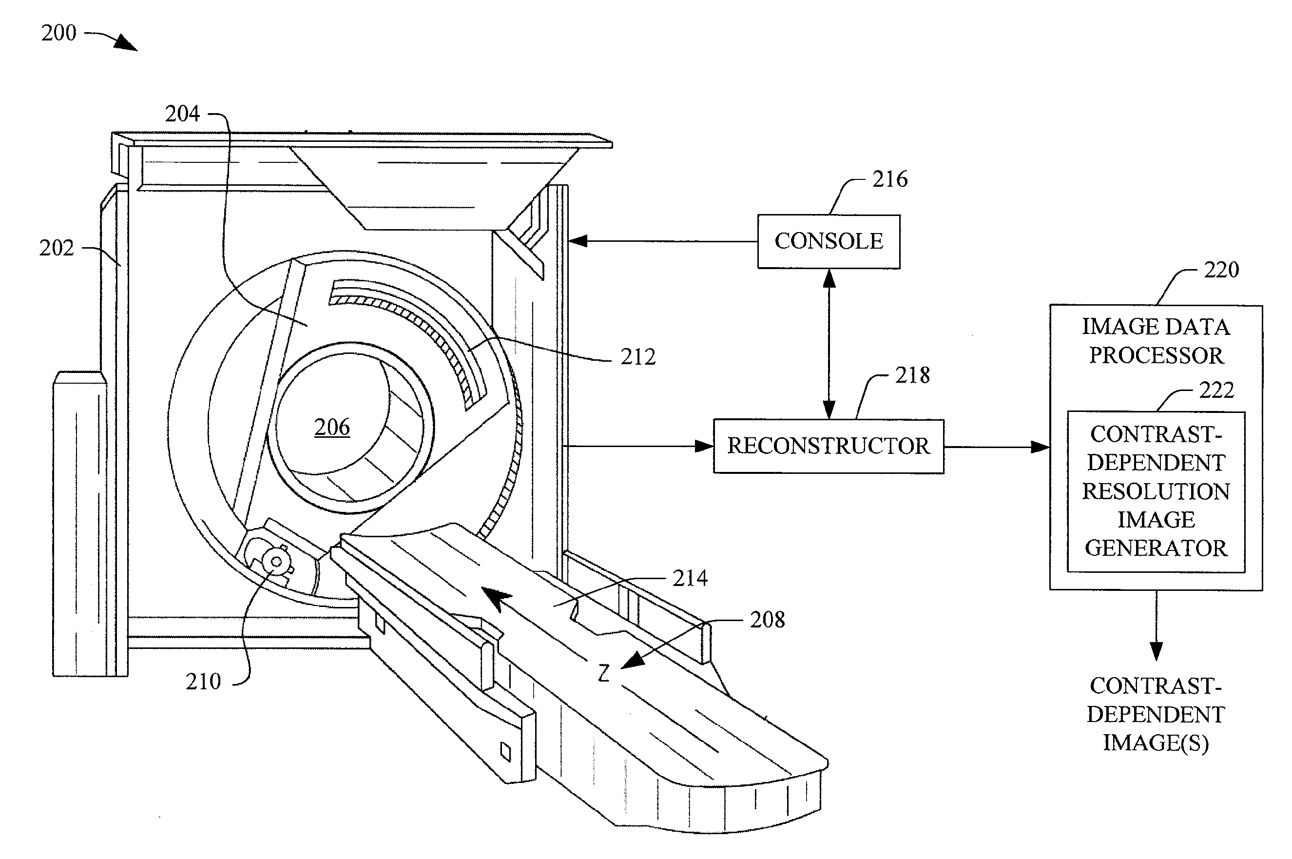
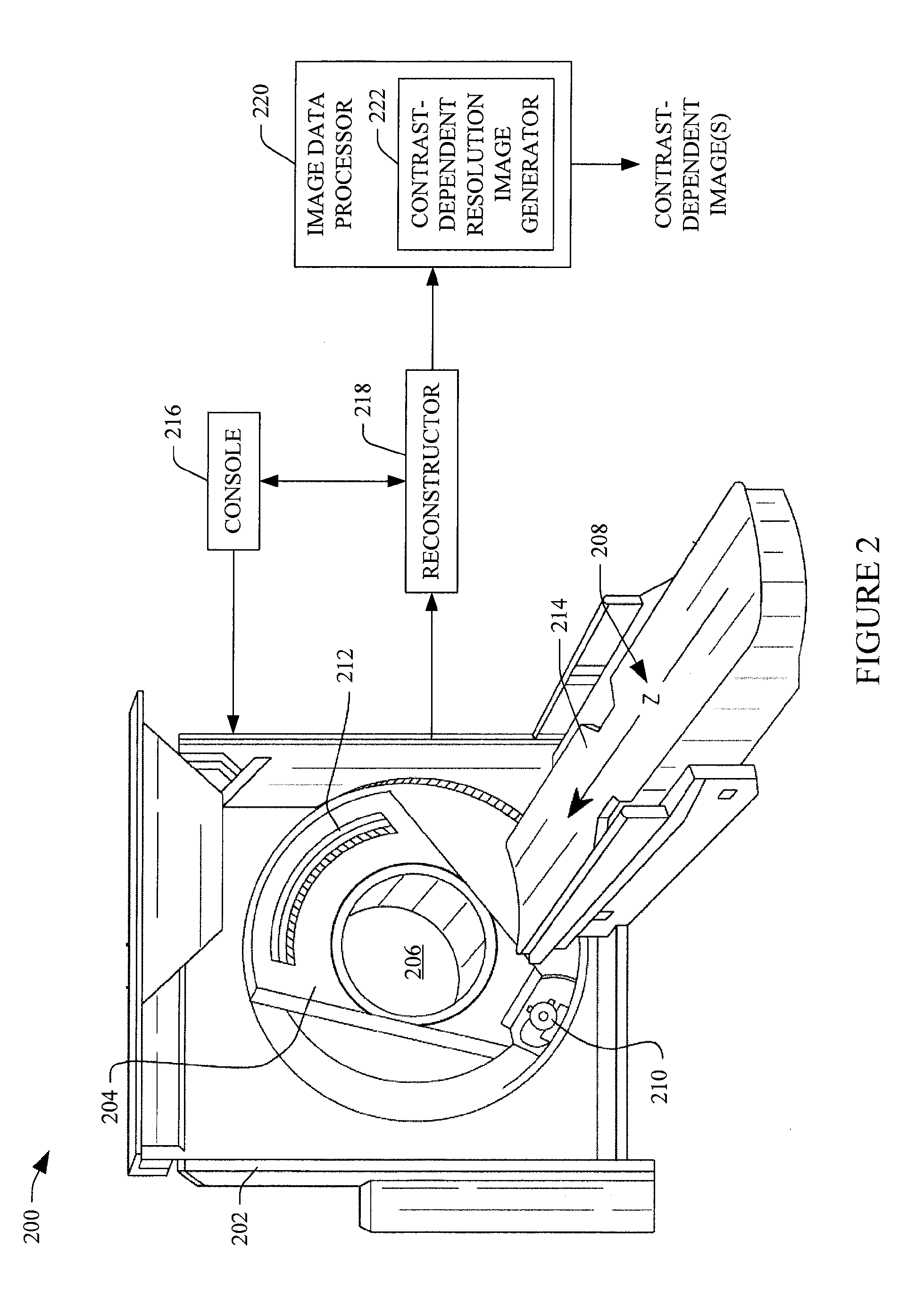
[0017]FIG. 2 illustrates an imaging system 200 such as a computed tomography (CT) scanner. The imaging system 200 includes a generally stationary gantry 202 and a rotating gantry 204. The rotating gantry 204 is rotatably supported by the stationary gantry 202 and rotates around an examination region 206 about a longitudinal or z-axis 208.

[0018]A radiation source 210, such as an x-ray tube, is rotatably supported by the rotating gantry 204. The radiation source 210 rotates with the rotating gantry 204 and emits radiation that traverses the examination region 206. A source collimator includes collimation members that collimate the radiation to form a generally cone, fan, wedge or otherwise shaped radiation beam.

[0019]A one or two-dimensional radiation sensitive detector array 212 subtends an angular arc opposite the radiation source 210 across the examination region 206. The detector array 212 includes a plurality of rows of detectors that extend along the z-axis 208 direction. The de...


PUM


Abstract

A method for processing one or more reconstructed images includes receiving a first reconstructed image having a first image resolution and receiving a second reconstructed image having a second image resolution. The first resolution is greater than the second resolution. The method further includes generating a contrast-dependent resolution image by combining the first and second reconstructed images single image so that the first reconstructed image contributes to a greater degree to the contrast-dependent resolution image for higher contrasts regions of the images and the second reconstructed image contributes to a greater degree to the contrast-dependent resolution image for lower contrasts regions of the images.

Description

FIELD OF THE INVENTION[0001]The following generally relates to generating an image, from reconstructed images, that includes contrast-dependent resolution and is described with particular application to computed tomography (CT), however, the following is also amenable to other imaging modalities such as hybrid PET / CT and / or MRI / CT systems, a digital x-ray system, and / or other imaging modality.BACKGROUND OF THE INVENTION[0002]A computed tomography (CT) scanner includes an x-ray tube mounted on a rotatable gantry that rotates around an examination region about a longitudinal or z-axis. The x-ray tube emits radiation that traverses the examination region and a subject or object therein. A detector array subtends an angular arc opposite the examination region from the x-ray tube. The detector array detects radiation that traverses the examination region (and the subject or object therein) and generates projection data indicative thereof. A reconstructor reconstructs the projection data ...

Claims


Application Information

Patent Timeline
IPC IPC(8): G06T11/00
CPCG06T11/003G06T5/50G06T11/008
Inventor BROWN, KEVIN
Owner KONINKLIJKE PHILIPS ELECTRONICS NV
Features
  • R&D
  • Intellectual Property
  • Life Sciences
  • Materials
  • Tech Scout
  • Unparalleled Data Quality
  • Higher Quality Content
  • 60% Fewer Hallucinations
Learn More