
Method and system to actively pitch to reduce extreme loads on wind turbine

a technology of wind turbines and active pitching, which is applied in the direction of propulsive elements, motors, propellers, etc., can solve the problems of short circuit, short circuit, and short circuit of durable wind turbines

Inactive Publication Date: 2014-01-16
ENVISION ENERGY DENMARK
View PDF3 Cites 17 Cited by
  • Summary
  • Abstract
  • Description
  • Claims
  • Application Information

AI Technical Summary

Benefits of technology

The present invention aims to reduce downtime loads on wind turbines. This is achieved by providing timely wind condition data at the present time on the turbine and around it using a LIDAR system. This allows for predicting near future wind conditions that the wind turbine will experience.

Problems solved by technology

In wind turbine, design constraints are often fatigue loads or extreme loads.
Furthermore, the foundation is most often designed to extreme load constraints.
Such standard approaches by the person skilled in the state of the art will however not lead to a durable wind turbine in such extreme environments.
The electrical cables extending from the rotor blade to the nacelle twist during the pitching which may cause the insulation on the electrical cables to break off resulting in a short circuiting.
If the flap actuator is located in the rotor hub, the pneumatic / hydraulic hoses extending into the rotor blade also twist during pitching which may cause them to buckle or rupture resulting in a failure.
These electrical cables twist during the pitching which may cause the insulation on the electrical cables to break off resulting in a short circuiting.

Method used


Image

  • Method and system to actively pitch to reduce extreme loads on wind turbine
  • Method and system to actively pitch to reduce extreme loads on wind turbine
  • Method and system to actively pitch to reduce extreme loads on wind turbine

Examples


Embodiment Construction

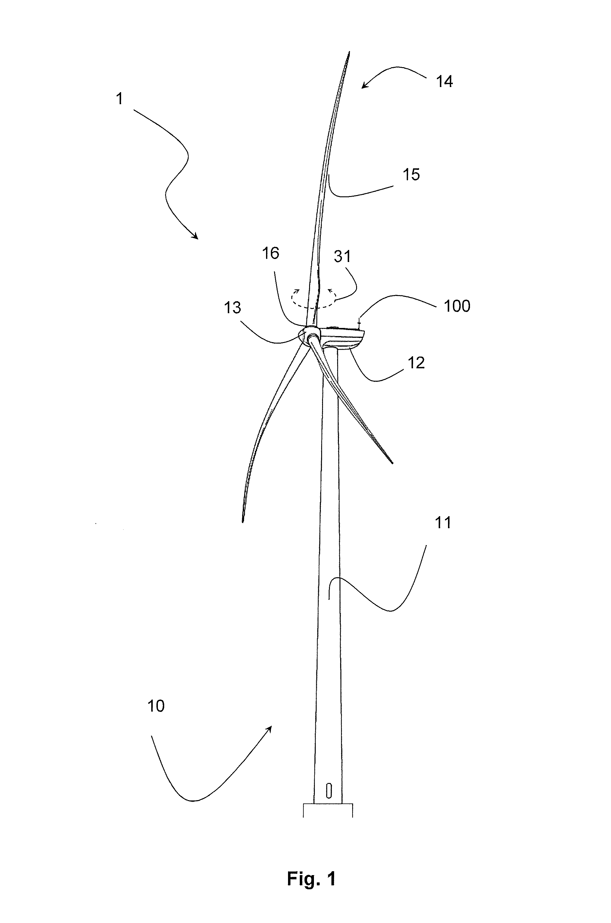
[0104]FIG. 1 shows a wind turbine 1 with a wind turbine system 10 comprising a tower 11, a nacelle 12, a hub 13, a rotor 14 with a set of rotor blades 15. The rotor blades 15 can be pitched by a pitching system 16.

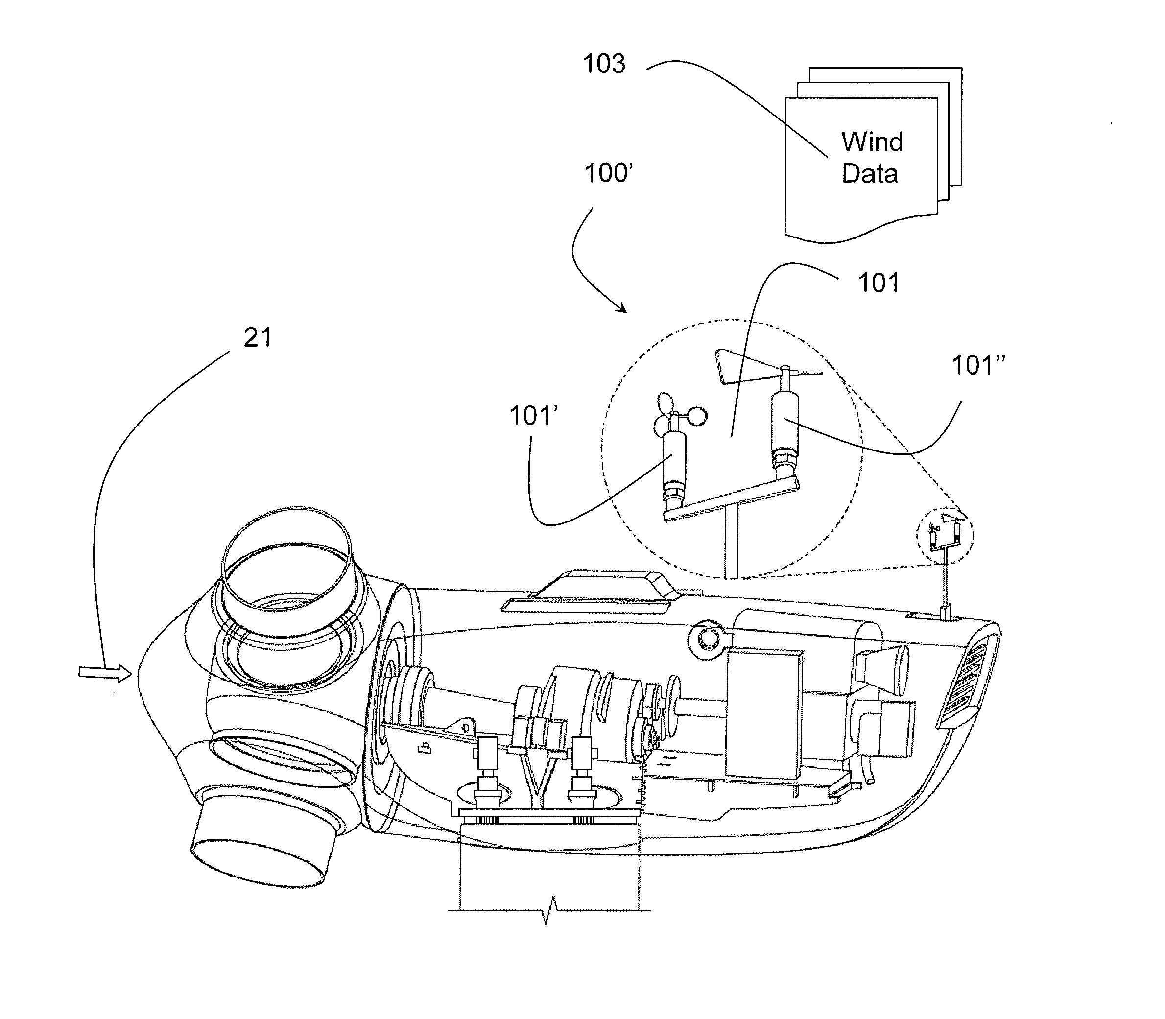
[0105]The wind turbine system 10 further comprises a sensor system 100 part of which is indicated here and which will be further exemplified.

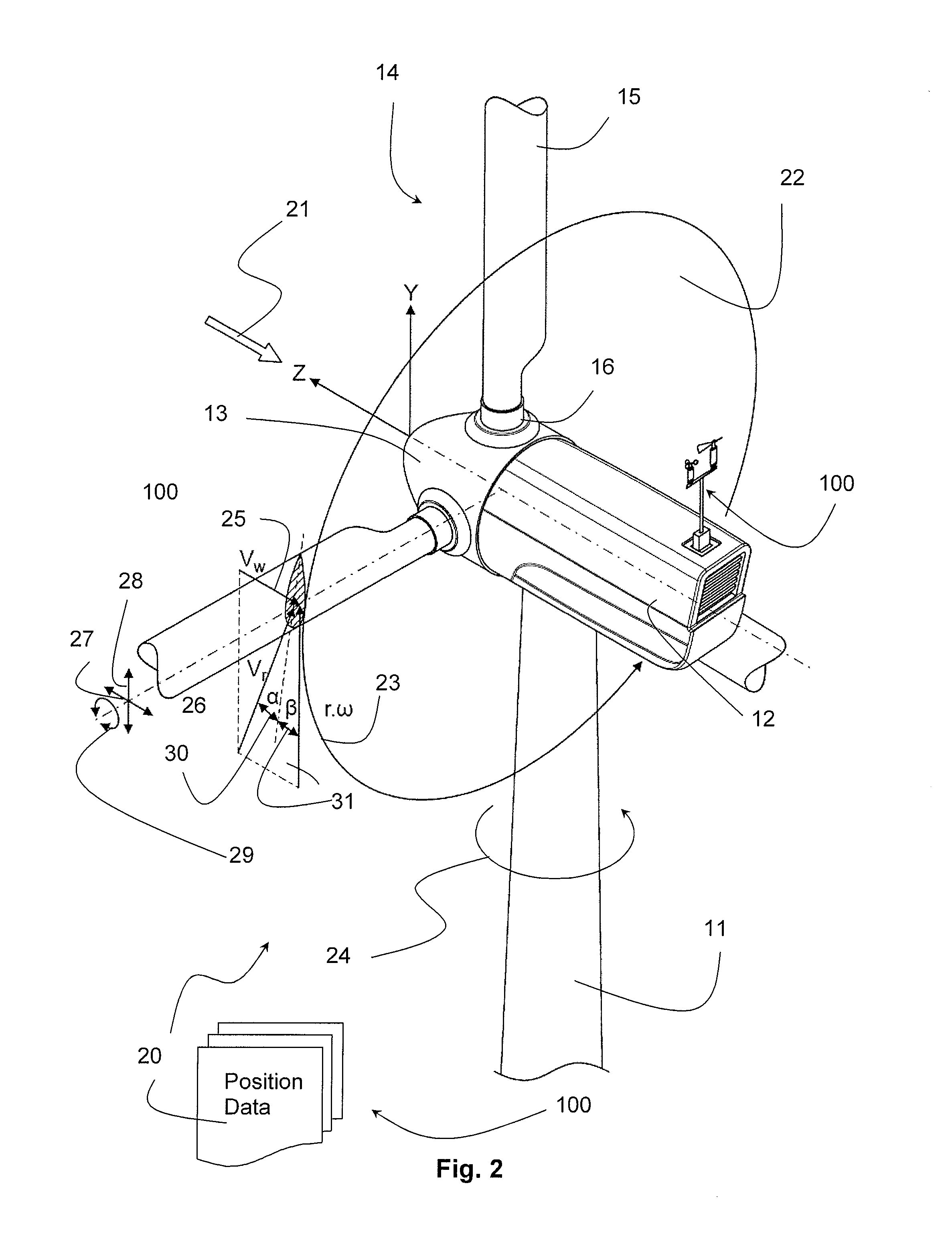
[0106]FIG. 2 shows definitions of angles, positions and co-ordinates of the rotor 14 and associated position data 20 as will be described.

[0107]The rotor 14 on the nacelle 12 is aligned to face the wind speed direction 21 so that the rotor 14 on the nacelle 12 faces the wind in the Z-direction and perpendicular thereon, the rotor 14 rotates in a X-Y-plane of rotation 22. At any given time, the rotor 14 is positioned in a rotor angle 23. Also at any given time, the nacelle 12 is in a given azimuth angle 24 relative to the tower 11.

[0108]Each blade 15 extends radially from the hub 13 or the Z-axis 21 in the X-Y-plane 22 and each blade 1...


PUM


Abstract

The present invention relates to a method of controlling an idling wind turbine in which wind condition data and wind turbine position data are collected by a sensor system, a control system computes an optimal pitch angle for a rotor blade of the wind turbine, and a pitching system continuously turns the rotor blades in the same direction in multiples of 360 degrees. The present invention further relates to a wind turbine with a sensor system including a wind sensor that measures wind condition data in the vicinity of the wind turbine, and a control system including a computer that executes a control algorithm and processes sensor input from the sensor system to compute an optimal pitch angle value for a rotor blade on the hub. This allows pitching the rotor blade into angle in which the mechanical loads of that rotor blade are reduced to a minimum when idling.

Description

BACKGROUND OF THE INVENTION[0001]1. Field of the Invention[0002]The present invention relates to a method of controlling an idling wind turbine in particular comprising a sensor system and a control system, and comprising the steps of measuring, comparing, computing and correcting the pitch angle of a wind turbine.[0003]2. Description of Related Art[0004]The present invention further relates to wind turbine with a sensor system comprising at least one sensor with a wind sensor configured to measure / detect wind condition data in the vicinity and preferably up-wind of the wind turbine and a control system comprising at least one computer with means for executing a control algorithm and configured to process sensor input from the sensor and to compute an optimal pitch angle value that results in a minimal mechanical load of least one rotor blade on the hub when the wind turbine is not producing power.[0005]In wind turbine, design constraints are often fatigue loads or extreme loads.[00...

Claims


Application Information

Patent Timeline
IPC IPC(8): F03D7/02
CPCF03D7/0224F03D7/0208F03D7/0268Y02E10/72F03D7/024F03D7/042
Inventor GRABAU, PETER
Owner ENVISION ENERGY DENMARK
Learn More