Dry-type cleaning chassis, dry-type cleaning device, and dry-type cleaning method

a cleaning chassis and cleaning technology, applied in the direction of household cleaners, tableware washing/rinsing machines, suction cleaners, etc., can solve the problems of high cost, large amount of solvents, heavy burden on operators and the environment, etc., to improve the working efficiency of cleaning operations, reduce the downtime caused by cleaning media exchange operations, and improve the effect of cleaning media

Inactive Publication Date: 2014-01-23
RICOH KK
View PDF2 Cites 3 Cited by
  • Summary
  • Abstract
  • Description
  • Claims
  • Application Information

AI Technical Summary

Benefits of technology

[0027]According to an aspect of the present invention, cleaning media exchange operations are performed when the cleaning media are not electrostatically adhered to the chassis. That is, energy of the cleaning media flown by a circulating air flow during cleaning operations is used to exchange the cleaning media. In this way, cleaning media may be quickly exchanged in a simple and reliable manner without stopping cleaning operations.
[0028]In turn, downtime caused by the cleaning media exchange operations may be reduced, working efficiency of the cleaning operations may be improved, and the required labor for exchanging the cleaning media may be reduced, for example.

Problems solved by technology

In this case, a large amount of solvent is used thereby incurring high costs and imposing heavy burdens on the operator and the environment.
However, in either case, a large amount of solvent is used to clean the cleaning object.
It is noted that in the dry-type cleaning device of the type described above, there may be a case where the type of cleaning media selected to be used according to the type of cleaning object is not suitable due to various conditions.
Also, there may be a case where the cleaning media cannot be smoothly discharged from the separation plate so that the cleaning capacity of the dry-type cleaning device may be degraded over time.
As can be appreciated, operations for exchanging the cleaning media are rather burdensome and affect the downtime of overall operations.
Although measures are implemented to vacuum up the cleaning media via the opening part in the above exchange method, a circulating air flow that is strong enough to remove the cleaning media adhered to the chassis by the electrostatic force is not generated so that complete removal of all the used cleaning media has been rather difficult.
Accordingly, in the above exchange method, exchange (replacement) of the cleaning media to new cleaning media may inevitably be incomplete.

Method used


Image

  • Dry-type cleaning chassis, dry-type cleaning device, and dry-type cleaning method
  • Dry-type cleaning chassis, dry-type cleaning device, and dry-type cleaning method
  • Dry-type cleaning chassis, dry-type cleaning device, and dry-type cleaning method

Examples


first embodiment

[0107]In the following, a dry-type cleaning chassis 50 according to the present invention is described with reference to FIGS. 1 through 10. It is noted that in the following descriptions of preferred embodiments of the present invention, the same reference numerals may be used to identify elements substantially identical to or corresponding to the elements of the configuration described above, and their descriptions may be omitted.

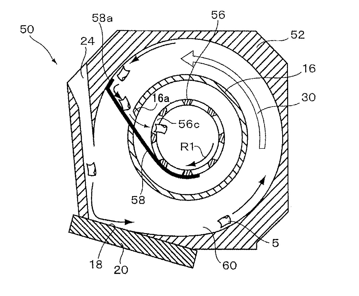
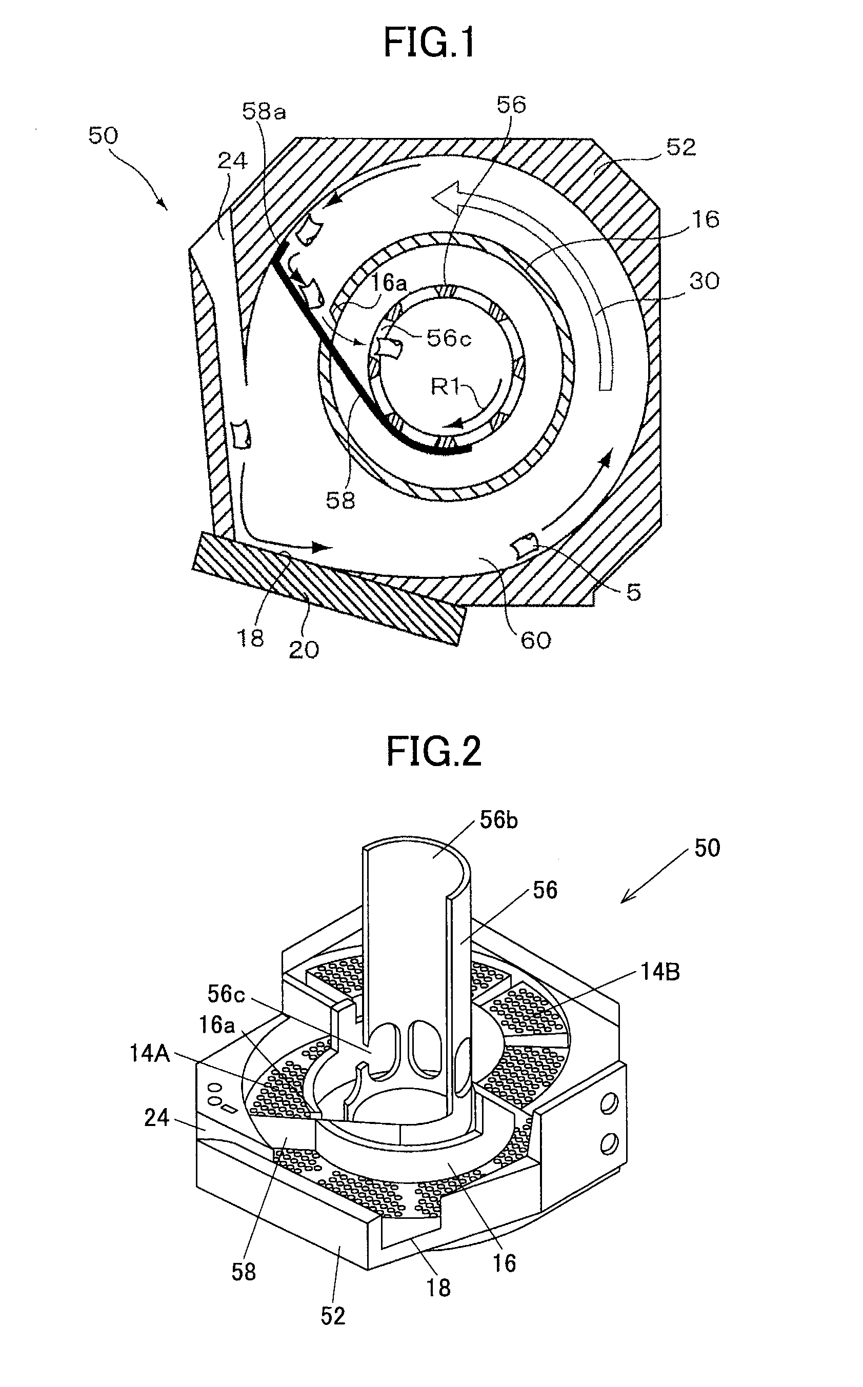
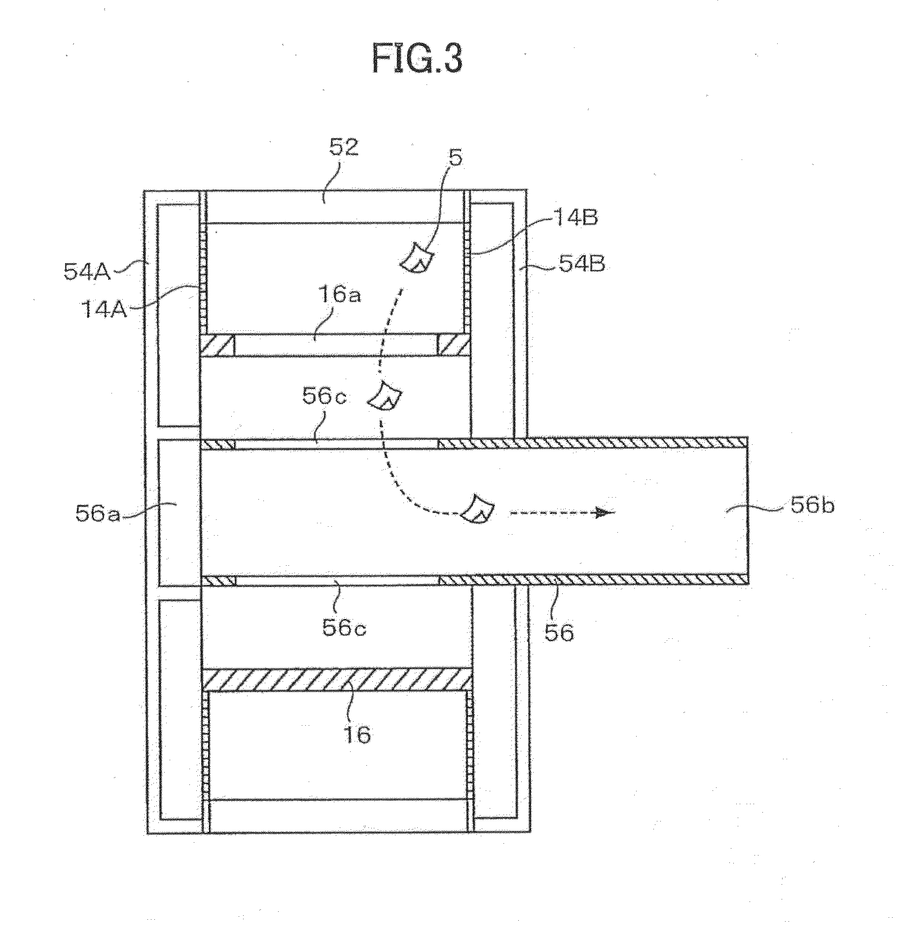
[0108]As illustrated in FIG. 6, the dry-type cleaning chassis 50 of the first embodiment includes a chassis body 52 having a through hole extending in the circulating axis direction, a cylindrically-shaped flow path limiting member 16 that is arranged at the center part of the through hole of the chassis body 52, separation plates 14A and 14B fixed at opposite sides of the chassis body 52 with respect to the circulating axis direction, outer covers 54A and 54B respectively covering the outer sides of the separation plates 14A and 14B, and a dust collectio...

second embodiment

[0147]For example, in one alternative embodiment (second embodiment) as illustrated in FIG. 11, a cleaning media discharge outlet 52a may be formed at the chassis body 52, and a cleaning media guide member 62 may be arranged to block the cleaning media discharge outlet 52a. In this embodiment, the cleaning media discharge outlet 52a is connected to a suction hose (suction port) 10a that branches out from the suction hose 10 of the suction unit 6.

[0148]The cleaning media guide member 62 is urged by a spring member 64 to be disposed at a position corresponding to an open position at which its tip end part 62a blocks the cleaning media discharge outlet 52a. Relying on the characteristic of the cleaning media 5 to fly toward the outer periphery side of the circulating flow path 60 due to centrifugal force, the length of the cleaning media guide member 62 is arranged so that it would block a portion of the circulating flow path 60 at the outer periphery side upon being moved to a dischar...

third embodiment

[0149]FIGS. 12A and 12B illustrate the present invention. The chassis configuration according to this embodiment is similar to that of the chassis 50 illustrated in FIG. 1 other than that it includes a cleaning media guide member 70 arranged at the chassis body 52 and does not have a rotating member for rotating the dust collection duct 56.

[0150]As illustrated in FIG. 12B, the cleaning media guide member 70 is urged by the spring member 64 in the outward direction (indicated by the arrow shown in FIG. 12B) so that its tip end part 70a may be prevented from protruding from the inner face of the chassis body 52.

[0151]An outer periphery side air flow 30a of the circulating air flow 30 circulates at a higher peripheral speed compared to an inner periphery side air flow 30b of the circulating air flow 30. As described above, centrifugal force causes the cleaning media 5 to fly toward the outer periphery side of the circulating flow path 60. When the suction unit 6 is in operation, a pull...


PUM


Abstract

A dry-type cleaning chassis includes an internal space in which cleaning media are flown, an opening part configured to be in contact with a cleaning object, an air inlet duct configured to introduce external air into the internal space, a suction port that vacuums the air introduced into the internal space from the air inlet duct and causes a circulating air flow to be generated in the internal space, a flow path limiting member that regulates a circulating axis of the circulating air flow within the internal space, a cleaning media discharge outlet that is in communication with an exterior of a circulating flow path of the circulating air flow and is configured to discharge the cleaning media from the circulating flow path to the exterior, and a cleaning media guide member that guides the cleaning media to the cleaning media discharge outlet.

Description

BACKGROUND OF THE INVENTION[0001]1. Field of the Invention[0002]The present invention generally relates to a dry-type cleaning device that cleans a cleaning object by having flying cleaning media come into contact (e.g., collide) with the cleaning object. More particularly, the present invention relates to a dry-type cleaning device that is configured to be placed in contact with a given cleaning region of the cleaning object to clean this region, a dry-type cleaning chassis used in the dry-type cleaning device, and a dry-type cleaning method using the dry-type cleaning device.[0003]For example, the present invention may be used to remove flux adhered to a so-called “dip pallet” or “carrier pallet,” which corresponds to a masking fixture used in a soldering process using a flow solder bath. Particularly, the present invention may be used to remove flux adhered to narrow areas such as the periphery of an opening or a side face of the cleaning object.[0004]2. Description of the Relate...

Claims


Application Information

Patent Timeline
Patent Type & Authority Applications(United States)
IPC IPC(8): B08B5/04B08B7/04
CPCB08B5/04B08B7/04B08B7/00B08B7/02B08B15/04
Inventor TANEDA, YUUSUKEFUCHIGAMI, AKIHIROTSUKAHARA, KOHJIMURAKAMI, KAKUJIMURATA, SHOZO
Owner RICOH KK
Why Eureka
Try Eureka