Laser machining device

a laser machining and laser beam technology, applied in laser beam welding apparatus, instruments, optics, etc., can solve the problems of affecting the power of laser tools, affecting the machining accuracy of laser beams, etc., to achieve simple and precise manner, small deflection angle, and simple and precise laser radiation deflection

Active Publication Date: 2014-01-23
TRUMPF LASERSYST FOR SEMICON MFG
View PDF17 Cites 9 Cited by
  • Summary
  • Abstract
  • Description
  • Claims
  • Application Information

AI Technical Summary

Benefits of technology

[0017]Preferably, at least a portion of the optical redirection means can be pivoted about at least one, preferably two, adjustment axis / axes. The laser radiation can thereby be coupled into the individual fibre cores of the optical-fibre cable in a reliable manner regardless of a geometric arrangement of the input-side optical coupling faces thereof with respect to the switching device. Positional tolerances of the optical fibre cores or the input-side optical coupling faces thereof can also be compensated for in a simple and precise manner.
[0018]The use of the prism enables particularly simple and precise deflection of the laser radiation, with in particular very small deflection angles also being able to be produced. The laser radiation can thereby also be coupled into fibre cores of the optical-fibre cable arranged close beside each other in a loss-free manner or without relatively large losses. According to an embodiment, the prism may be (permanently) arranged in the beam path of the laser radiation. In this instance, the laser radiation may be coupled into the individual fibre cores of the optical-fibre cable by means of simple rotation of the prism about the adjustment axes thereof. This structural type is advantageous, for example, in an optical-fibre cable in which the fibre cores are arranged at the input-side end of the optical-fibre cable in a circular manner around the longitudinal axis of the optical-fibre cable.
[0019]In the structurally simplest case, the prism can be moved into the beam path of the laser radiation, in particular pivoted therein. The laser radiation, for example, in an optical-fibre cable having only two fibre cores, can thereby be deflected in a simple manner and coupled into another fibre core, respectively.

Problems solved by technology

This does not promote a compact structural type.
In addition, in particular when the optical-fibre cables are changed, there is produced considerable operational complexity and in practical terms a not inconsiderable risk of contamination, for example, of optical coupling faces of an optical fibre core of the individual optical-fibre cables, which can lead to occurrences of impairment of the power of the laser tools.

Method used


Image

  • Laser machining device
  • Laser machining device
  • Laser machining device

Examples


Embodiment Construction

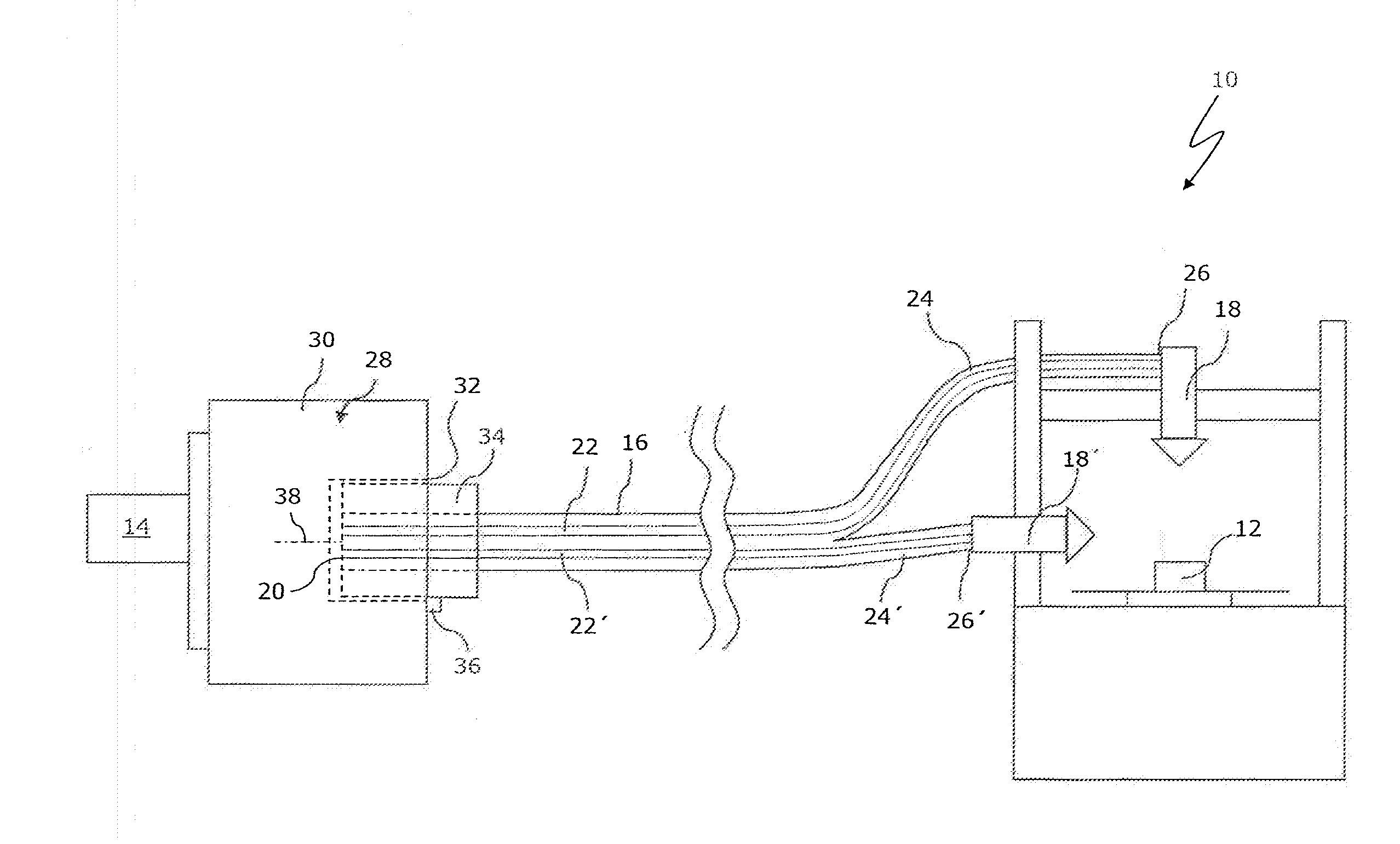
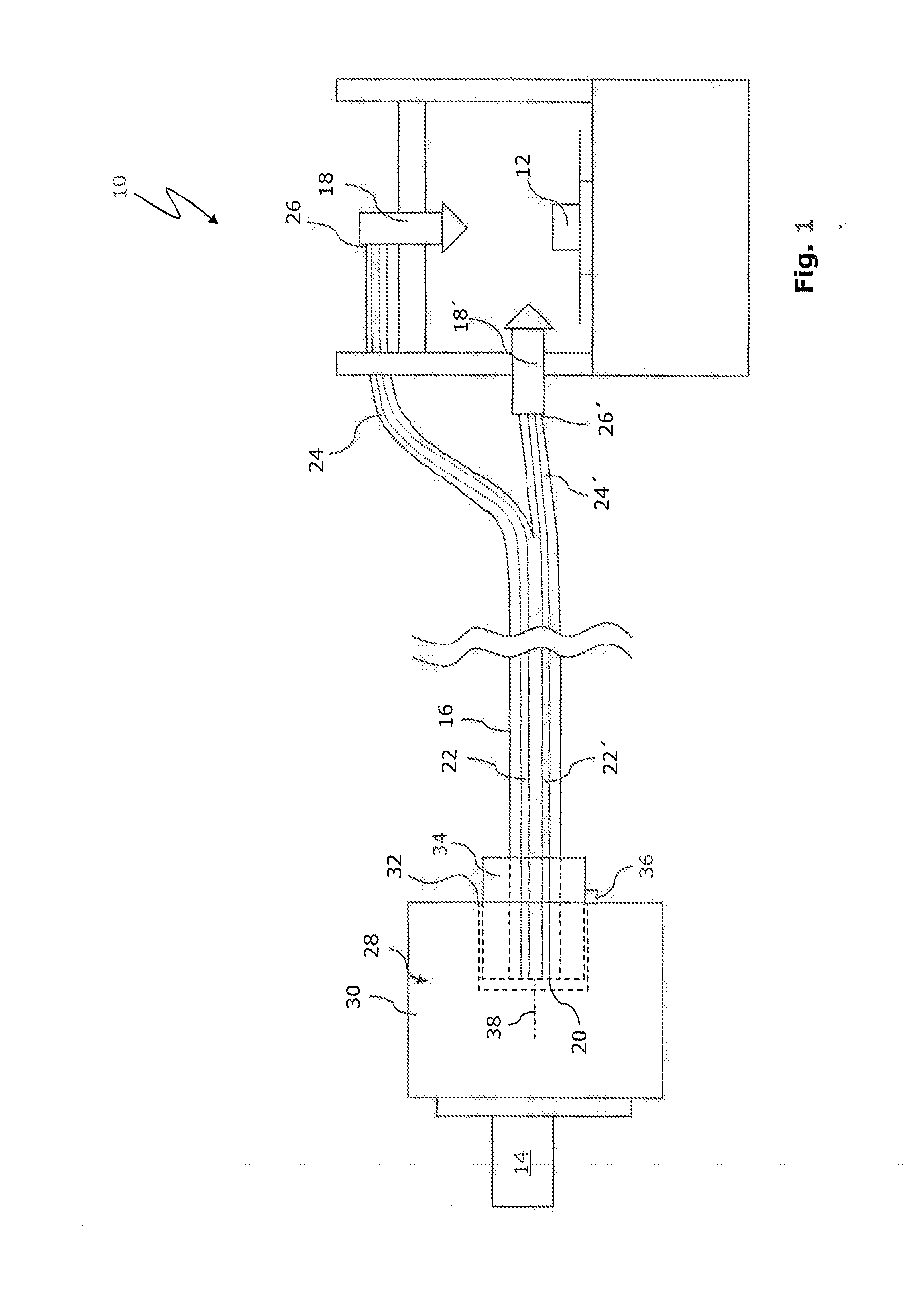
[0028]FIG. 1 shows a laser machining device 10 for a laser machining operation of a workpiece 12. The laser machining device 10 has a laser 14 for producing laser radiation, which can be supplied to two laser tools 18, 18′ by means of a substantially Y-shaped optical-fibre cable 16.

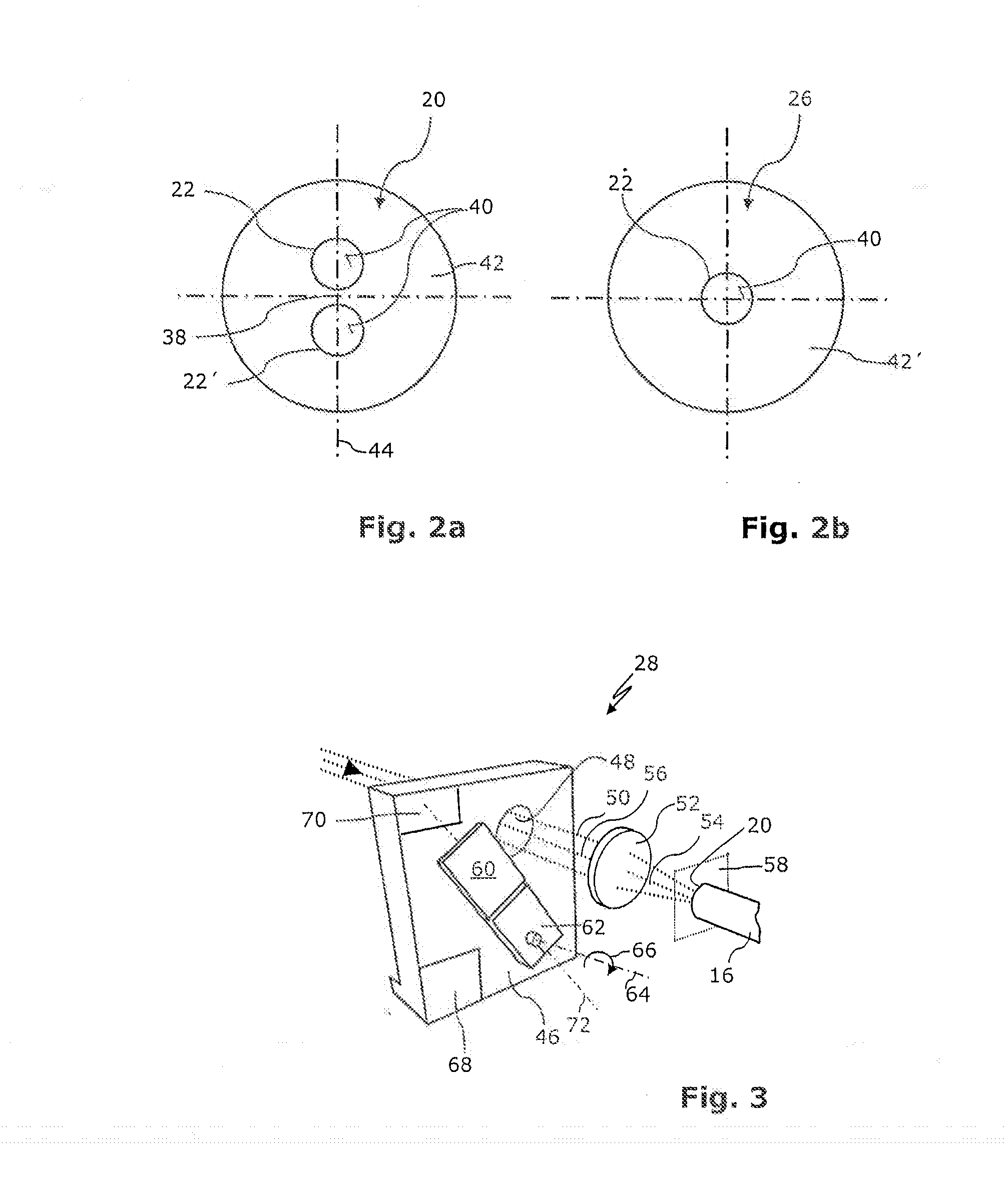
[0029]The optical-fibre cable 16 has an input-side end 20 having two optical fibre cores 22, 22′, which are each illustrated with dashed lines. The optical-fibre cable 16 is branched in terms of its path into two optical-fibre cable branches 24, 24′ and consequently has two separate output-side ends 26, 26′ each having one of the optical fibre cores 22, 22′. The output-side ends 26, 26′ or the optical fibre cores 22, 22′ are each connected to one of the laser tools 18, 18′.

[0030]A switching device 28 which is arranged downstream of the laser 14 serves to selectively couple the laser radiation produced by the laser 14 into one of the optical fibre cores 22, 22′ of the optical-fibre cable 16, respectively. ...


PUM

PropertyMeasurementUnit
torsion angleaaaaaaaaaa
rotation angleaaaaaaaaaa

Abstract

There is proposed a laser machining device (10) for a laser workpiece machining operation, having a laser (14) for producing laser radiation (50), and having at least two laser tools (18, 18′), to which the laser radiation (50) can be supplied by means of an optical-fibre cable (16). According to the invention, the optical-fibre cable (16) has an input-side end (20) having at least two optical fibre cores (22, 22′) and a plurality of output-side ends (26, 26′) each having one of the optical fibre cores (22, 22′), the optical fibre cores (22, 22′) each being connected to one of the laser tools (18, 18′). A switching device (28) is preferably provided for selectively coupling the laser radiation (50) in one or more of the optical fibre cores (22, 22′) of the optical-fibre cable (16).

Description

BACKGROUND OF THE INVENTION[0001]1. Field of the Invention[0002]The invention relates to a laser machining device for a laser workpiece machining operation, having a laser for producing laser radiation, and having at least two laser tools, to which the laser radiation can be supplied by means of an optical-fibre cable.[0003]2. Description of Related Art[0004]EP 1 591 189 A1 disclosed, for example, a laser machining device of this type in which the laser radiation produced by the laser can be supplied to the individual laser tools by means of a plurality of optical-fibre cables which are connected thereto. The optical-fibre cables require in each case at the laser side separate connections which, owing to a respective cross-section of the optical-fibre cables or the connection plugs thereof, are arranged with a predetermined minimum spacing from each other. This does not promote a compact structural type. In addition, in particular when the optical-fibre cables are changed, there is ...

Claims


Application Information

Patent Timeline
Patent Type & Authority Applications(United States)
IPC IPC(8): B23K26/067
CPCB23K26/0673B23K26/0884G02B6/32G02B6/3528G02B6/355G02B6/4296B23K26/067B23K26/08B23K26/064G02B6/04
Inventor BROCKMANN, RUDIGERHUONKER, MARTIN
Owner TRUMPF LASERSYST FOR SEMICON MFG
Why Eureka
Try Eureka